SMALL SAWMILL IMPROVEMENT equipment) *
advertisement
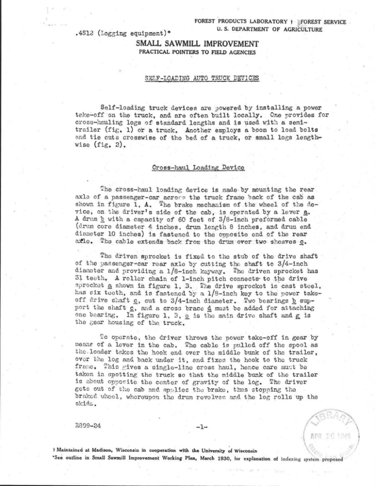
.4S12 (Logging equipment) * FOREST PRODUCTS LABORATORY t 'FOREST SERVIC E U . S. DEPARTMENT OF AGRICULTUR E SMALL . SAWMILL IMPROVEMEN T PRACTICAL POINTERS TO FIELD AGENCIES SS ? LOADING, AU '0 T LfCIC7F,7C Fell-loading truck devices are powered by installing 'a power ' One provides for take'-off on the truck, and are often built locally . cross-hauling logs of standard lengths and is used with a semi trailer (fig . 1) or a truck . Another employs a boom to load bolt s and tie cute crosswise of the bed of a truck, or small logs lengthwise (fig, 2) . Cross-haul Leading Devic e The .cross-haul loading device is made by .tnounting the rea r axle of a passenger-car acroes the truck frame back of the cab'a s shown. in figure 1, A . T he brake mechanism of the wheel of the de vice, on the driver t side of the cab, is operated by a lever a . A dram b With a capacity of 60 feet of 3/8-inch preformed cabl e (drum core diameter 4 inches, arum length 8 inches, and drum en d diameter 10 inches,) is fastened to the opposite end of the rea r mac . uhe cable extends-b .Ck .1 fr'om.t ^:e -d m•-fiver two sheaves .-c. s The driven_ sprocket is fixed to the stub of the drive shaf t of the passenger-mr rear axle by cutting the shaft to 3/4-inc h diameter and providing a• . 1/8-inch keyway . The driven sprocket ha s 31 teeth_ . A roller chain of 1-inch pitch conneets- to the driv e s p rocket a shown in figure 1, 3 . The drive sprocket is cast steel , has six tooth, and is fastened bY a 1/8-inch key to the power take off drive shaft c, cut to 3/4-inch diameter . Two bearings b support the shaft c, and a cross brace d must be added for attachin g one bearing . In figure 1, 5, ' is the main drive shaft and € i s the gear housing of the truck . 7 o o p erato ., the driver throws the power take-off in gear b y meant of a lover in the cab . . The cable is pulled off the spool a s the .loader takes the hook end over the middle bunk of the trailer , over_ the log and back under it, and fixes the hook to the truc k fra o, This ;dives a single-line cross haul, hence care must b e taken in spotting the truck so that the middle bunk of the traile r is about opp oeite the center of gravity of the log . The drive r gets out of the cab and apsliec the brake, thus stop p ing th e braked wheel, whereupon the drum revolve and the log rolls up th e skids . 8899-24 -1- t Maintained at Madison, Wisconsin in cooperation with the University of Wisconsi n "` See outline in Small Sawmill Improvement Working Plan, March 1930, for explanation of indexing system proposed Boom-type Loading Devic e Boom-type equipment is widely used in the Lake States i n loading and unloading 100-inch bolts, tie cuts, and smaller logs , The boom may be either fixed' or swinging . Fixed Boo m The less expensive installations have a power take-off and drum mechanism' and have a wood frame and boom . The wood is of a high density species, such as oak, ash, or elm . Figure 2 shows a fixed-boom loading device installed on' a truck but does not show the power take-off mechanism which i s similar to that shown in figure 1 . In figure 2, two 4-inch b y 5-inch uprights a extend 10 feet above' the-truck frame i.mmediately behind the cab . A 4-inch by 6-inch cross member b is fixed between ' the uprights approximately 6 feet 8 inches above the frame, A 4 inch by 4-inch booth c, long'onough•to extend approximately half th e truck bed length, is clevis-clamped to the midpoint of the cros s member b . The union of the cross member and uprights is reinforced . with angle iron . The bases of°the uprights are clamped to the to p of the truck frame and likewise are reinforced by Angle iron and b y a 2-inch by 4-inch brace d, one end being fastened about 2 fee t Above the base of the upright -and the other fastened to the truc k frame about 2 feet behind the uprights . Three-fourths-inch cabl e ' bracing e is placed as follows : from the outer end of the boom , back to each upright at the juncture,of the cross member, from eac h end of the cross member diagonally to the bottom of the opposit e upright, and from the outer end of the boom over the top of eac h upright, over the cab and hood to the car frame under the radiator . T he power cable is threaded through sheaves at the base and end - . of the boom . Swinging Boo m In this installation, the boom may pivot from the boom fram e at one definite point, usually half across the truck (details no t shown), or may pivot from any of several points across the truc k (fig . 3) permitting both a greater reach laterally and a more posi tive pull when the boom is in a lateral position . This arrangement permits easy swinging of the load to or way from the truck . If tie cuts`or'ldgs are hauled, a crotch line-end hook com bination is used ; for bundles of bolts, the single cable and hoo k prevail, To operate, the power take-off mechanism is engaged an d the power take-off gear box 'lever shifted from neutral to low ;_wit h the truck spotted conveniently for loading or unloading . For material R899•-24 to be loaded crosswise of the `ruck bed, the truck is usually , place d parallel to the bolts ; for longer material, the long axis of th e truck bed is parallel to the logs . The cable i-a polled off the .:inc h by the ground man . In loaaing pulpwood, about one .-fourth-cord to a sling is held by a single wrap . With tie ruts or logs, sin, le etiok s are gripped by end, hooks . The ground man then manipulates the brake cables to elevate the-load, and suspend it while it swings over th e truck and is released onto the truck bed, The load is raided by- a second men to its position on the truck . Centribl.ted by Small-mill Specialist June 1945 w 1 T , .-2ec. al ac motaledgmcnt is matte to 7, axon, -~eGion 9, - ''ores t ~ervice, for the description of tip fixed boom show_z 1116 to y,, 3 , >.owes, Howes Lu :ab Yr Corporation, . pc~rte , Ina ., for uetai is o f the Dover cross-haul device . R89'Vr24 A B LEGEND : a-BRAKE LEVER b-DRUM FOR CABL E C- SHEAVES FOR CABL E a-SPROCKE T b-BEAR/NGS FOR POWER TAKE-OFF SHAF T C-POWER TAKE-OFF SHAF T d-SPEC/AL METAL CR055 SUPPOR T e-MA/N DRIVE SHAFT OF TRUC K f-SUPPORT OF MAIN DRIVE SHAFT 9-GEAR HODS/N G B Figure 1 .--Cross-haul loading device mounted on truck frame . Z M b3261 F 0 LEGEND FOBFIGURE 3 _nee a - Tie rod 3/4 inch by 7-1/2 feet welded to the top of boom d an d pipe b . b - 3-1/2-inch standard p ipe extending 1 foot above cross fitting . c - Chain . U-bolt connection limits arc of travel of boom . d - Boom, 3-1/2-inch standard pine 8 feet long . e - 3/8-inch preformed cable for hoist . f - Iron bar 1/2 inch by 4 inches by 3 feet 3 inches welded tc up rights i-i and plates g .-E . Top of bar is 4 inches below to p of upright . Seven holes are drilled as shown for sheave hook . g - 3/8-inch metal plate welded to upright i and to top member n . h - Chain, limits arc of travel of boom . i - Derrick frame upright made of 3-1/2-inch standard pipe in tw o sections to allow dernounting . Top of truck frame to to p of ferrule , i is 6 feet . Top of ferrule j, to top of upright is 2 feet, Total height must not exceed state highway regulations . • - Ferrule made of 4-inch standard pipe 1 foot long, welded to uppe r ((The top of , cannot excee d end of lower section of upright . the height of the garage door where the truck is housed . ) k - 3/8-inch plate welded to frame upright and boltea to truck fram e with three 3/4-inch bolts . 1 - U-bolt support of housing in front of gear-shift box . The suppor t is bolted to an angle-iron strap attached to the cross membe r of the truck frame . m - Gear-shift box . n - Steel plate 1/2 inch by 6 inches by 2 feet 10 inches welded t o plates and to cross braces, so that the angle between the uprighte i-i and plate n in approximately 100° . Nine holes ar e spaced at approximately 4-inch intervals drilled to take the 1-1/4-inch stem zz . o - Stool -p ate 1/2 inch by 2 inches welded to n and tog to reinforce n and p rovide additional bearing for zz . Iron braces 112 inch by 1-3/4 inches welded to uprights . • g -- Brake cable, 3/16 inch p reformed, extending from brake leve r through sheave attached to truck frame, thence over sheave nea r top of derrick frame with the free end extending as required t o be within reach of loader . 3 - Idler roll for hoist cable . s - 2-inch by 2-inch angle-iron su pp orts for power take-off equipment . - Metal plate supuortin ; roar-axle housing . u - 3/4-inch U-bolt sup sorting rear-axle housing . v_ - Hubs and brake equiement of rear axle . w - Lever arm for brake operation . x - Drum for hoist cable . Core 5 inches in diameter b-r 6 inches long . Cross for 4-inch pipe . • z - Steel plate welded to cross . zz - Stool stern 1-1/4 inahel in diameter yeas ; :ling through and welded t o z and welded to the top of the cross so as to center d. at right angles to the long axis of d . R899-24 a) N A a) • C b e a) a) o o A • -+ • ai +~ b 4. Ca m -1 • .4.A' 0 b a <41 Va a .H d C I~ • 4. 4. .) • a) • b c. 4. 4. 0 q 7 a) ; a R. •N • .i > > c8 O as rl +i C a ▪ at o O 0 +) a) a) d d a) +a GI WI a) .0 O O 'd E a) E > cS o c) E •> • a) ~ A 4. o O 3 a) ) . U > Ca L Q) c0 U +` b ,i q o ca • al o a) .4-41 +•) f~ I 0 C a) O 6 E o •.4 a E .. A a 0II > a1d I 0C d a) q -1 d a) : C a ca, c. o ''Cl d .- I a +~ 6) x 4-4 o o ▪ C Cd UI cd u) C a r1 0 o - •.I I d a d m x a) > Cd A a) )-) I ri O 0 . L. d C. d C ~ U I ;' a) a ~Q C9 b 3 C a) f. d In a) C P. m 0 ) U a w4 . id aocal o a 4,4
