MASSACHUSETTS INSTITUTE OF TECHNOLOGY
2.71/2.710 Optics
HW5
Spring ’14
Posted March 31, 2014, Due April 9, 2014
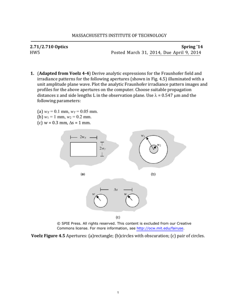
1. (Adapted from Voelz 4-4) Derive analytic expressions for the Fraunhofer field and
irradiance patterns for the following apertures (shown in Fig. 4.5) illuminated with a
unit amplitude plane wave. Plot the analytic Fraunhofer irradiance pattern images and
profiles for the above apertures on the computer. Choose suitable propagation
distances z and side lengths L in the observation plane. Use = 0.547 m and the
following parameters:
(a) wX = 0.1 mm, wY = 0.05 mm.
(b) w1 = 1 mm, w2 = 0.2 mm.
(c) w = 0.3 mm, s = 1 mm.
© SPIE Press. All rights reserved. This content is excluded from our Creative
Commons license. For more information, see http://ocw.mit.edu/fairuse.
Voelz Figure 4.5 Apertures: (a)rectangle; (b)circles with obscuration; (c) pair of circles.
1
2. (Adapted from Pedrotti 11-14) Retina Display is a brand name used by Apple which
they claim have a high enough pixel density that the human eye is unable to notice
pixelation at a typical viewing distance. Let’s find the required pixel size based on
principle of diffraction. Assume that the pupil diameter of a normal eye typically can
vary 2 to 7 mm in response to ambient light variation.
a. What is the corresponding range of distance over which such an eye can detect
the separation of objects 1 mm apart.
b. Experiment to find the range of distances over which you can detect the
separation of lines placed 1mm apart. Use the results of your experiments to
estimate the diameter range of your pupils.
c. Now we assume the screen of i-Phone is placed at 25cm away from the eye (you
may recall this is so called the nearpoint of the eye), estimate the maximum size
of pixels on the screen you would not notice the pixilation effect.
3. Newton’s Rings: The following figure illustrates a setup used for testing plano-convex
lenses using a famous interference effect, known as Newton’s rings. A plano-convex lens
(n=1.5, thickness t= 1cm, and radius of curvature R=20cm) is placed on a flat mirror,
and illuminated at normal incidence with a plane monochromatic light at wavelength
=500nm. For the approximation, assume the path difference between the two
reflected beams (one at the curved surface of the plano-convex lens and the other at the
mirror surface) is much smaller than the radius of curvature R of the lens, so we are
looking at the inner zones of Netwon’s rings.
CCD Detector
x
Beam
Splitter
Incoming
plane wave
Plano-Convex
Lens
Flat
Mirror
2
R
Plano-Convex
Lens
x’
h(x’)
Flat
Mirror
a) Assume both the plano-convex lens (n=1.5) and the beam splitter are large enough to
accommodate the entire lateral width of the expanding paraxial wave, write an
analytical expression for and sketch the interference pattern as function of the
coordinate x at the observation plane (CCD detector).
b) Calculate the radius of 10th bright ring on the CCD detector.
c) Explain how this Newton’s ring pattern would change if the illumination beam tilted
by a small angle .
4. A blazed glass grating (index of refraction n=1.5) displays a surface shaped like a
sawtooth, as shown in the following figure. The pitch of the tooth is 2.5 μm.
Period
2500nm
Blazed
grating
n=1.5
+1st order
Inefficient
diffraction
0th order
Inefficient
diffraction
h
-1st order
Efficient
diffraction
a) Find the optimum height h that maximizes the peak intensity of the -1 order
diffracted light for incident wavelength = 532nm.
b) Using the grating height from a), calculate the steering angle of the -1 order
diffracted beam for the following wavelengths: = 488nm (Blue), 532nm (Green),
and 633nm (Red).
3
5. Diffractive lens (Adpated from Goodman 5-13, 2.710 only): A diffracting
structure has a symmetric amplitude transmittance function given by
1 1
𝑟
𝑡(𝑟) = [ + cos(𝛾𝑟 2 )] 𝑐𝑖𝑟𝑐 ( )
2 2
𝑅
The grating is placed at the plane z = 0 and illuminated by an on–axis plane wave
𝐸(𝑥, 𝑧 = 0) = 𝐸0
a) Show that this grating also possess focusing function.
b) Determine the focal length of this grating(Hint: you may compare the
𝑟2
𝑟
transmittance function with that of a thin lens 𝑡(𝑟) = 𝑒𝑥𝑝 [−𝑖𝑘 2𝑓] 𝑐𝑖𝑟𝑐(𝑅))
c) What are the limitations of using this diffractive grating as an imaging element for
polychromatic objects?
4
MIT OpenCourseWare
http://ocw.mit.edu
2.71 / 2.710 Optics
Spring 2014
For information about citing these materials or our Terms of Use, visit: http://ocw.mit.edu/terms.


