Document 13555020
advertisement

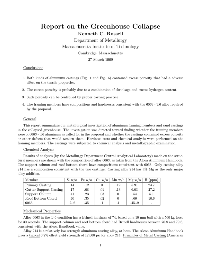
Report on the Greenhouse Collapse Kenneth C. Russell Department of Metallurgy Massachusetts Institute of Technology Cambridge, Massachusetts 27 March 1969 Conclusions 1. Both kinds of aluminum castings (Fig. 1 and Fig. 5) contained excess porosity that had a adverse effect on the tensile properties. 2. The excess porosity is probably due to a combination of shrinkage and excess hydrogen content. 3. Such porosity can be controlled by proper casting practice. 4. The framing members have compositions and hardnesses consistent with the 6063 - T6 alloy required by the proposal. General This report summarizes our metallurgical investigation of aluminum framing members and sand castings in the collapsed greenhouse. The investigation was directed toward finding whether the framing members were of 6063 - T6 aluminum as called for in the proposal and whether the castings contained excess porosity or other defects that would weaken them. Hardness tests and chemical analysis were performed on the framing members. The castings were subjected to chemical analysis and metallographic examination. Chemical Analysis Results of analyses (by the Metallurgy Department Central Analytical Laboratory) made on the struc­ tural members are shown with the composition of alloy 6063, as taken from the Alcoa Aluminum Handbook. The support column and roof bottom chord have compositions consistent with 6063. Only casting alloy 214 has a composition consistent with the two castings. Casting alloy 214 has 4% Mg as the only major alloy addition. Member Primary Casting Gutter Support Casting Support Column Roof Bottom Chord 6063 Si w/o .14 .17 .41 .40 .2-.6 Fe w/o .12 .08 .23 .35 .35 Cu w/o 0 .01 .03 .02 .1 Mn w/o .12 .13 0 0 .1 Mg w/o 5.91 6.03 .54 .66 .45-.9 H (ppm) 24.7 27.2 5.1 10.6 - Mechanical Properties Alloy 6063 in the T-6 condition has a Brinell hardness of 74, based on a 10 mm ball with a 500 kg force for 30 seconds. The support column and roof bottom chord had Brinell hardnesses between 76.8 and 79.6, consistent with the Alcoa Handbook value. Alloy 214 is a relatively low strength aluminum casting alloy, at best. The Alcoa Aluminum Handbook gives a typical 0.2% offset yield strength of 12,000 psi for alloy 214. Principles of Metal Casting (American 1 Foundryman’s Society, McGraw Hill, 1967) gives a minimum yield of 9,000 psi for this alloy, but note that yield strength is to be determined only if specified in the contract or purchase order. Neither the proposal, nor the purchase order for the greenhouse made any specifications on the castings. The accepted method for determining the strength of castings is to cast a tensile bar and then test it. This was of course impossible in this case. Microstructure Evaluation of the castings was mainly by means of metallographic examination. Macroscopic examina­ tion of the failed castings indicated extensive porosity, and both the gutter support casting (Fig. 1) and two primary castings (Figs. 5, 10) were sectioned near the fracture surfaces for microscopic examination. Fig. 2 is a photo macrograph of a section of the gutter support, wherein the white regions are voids. Porosity is extensive, and many of the finer pores are not visible. Figs. 3 and 4 show the porosity at the edge of the casting in the as-polished and the etched conditions. The pores are partly angular and partly rounded. Figs. 6 and 7 are two sections of the same primary casting (Fig. 5) and Fig. 11 is a section of another primary casting (Fig. 10). Extensive white regions, denoting porosity are visible in all three sections. Figs. 8 and 9 show the interior of the primary casting in Fig. 5. Extensive porosity is again seen, of the partly angular, partly rounded, geometry. The photomicrographs presented are typical, and do not represent the most porous regions. The void distribution is highly irregular, and in some regions a dozen or more voids are clustered together, giving a very weak region. The gutter support appears to have fractured in part through such a cluster of voids. The porosity is generally worst near the casting surface. However, since the critical region of the primary casting is less than 1/4” thick these surface effects extend across much of the load bearing section. Discussion Principles of Metal Casting states that Alloy 214 is one of the poorest sand-cast aluminum alloys with respect to resistance to hot-cracking, pressure tightness, fluidity, and the tendency for solidification shrink­ age. Further, molten aluminum has a well-known tendency to absorb hydrogen from moisture in the air, mold, or from the charged material, with resulting porous castings. However, proper melting procedure will remove the hydrogen and proper mold design will minimize porosity due to shrinkage. The book Aluminum (American Society for Metals, Metals Park, Ohio, 1967) indicates that hydrogen in aluminum alloys should be in the range 0.2 - 0.4 ppm (parts per million) for acceptable commercial sand castings. We compare this to the 24.7 and 27.2 ppm found in the subject castings, and conclude that the castings were very high in hydrogen. It is well-known (see for example Principles of Metal Casting, 1967) that pure shrinkage porosity is generally angular and pure gas porosity is generally rounded. It is also known that the two effects reinforce, and frequently a pore due to shrinkage will expand due to gas pressure. This gives partly angular - partly rounded pores of the type shown here. The high hydrogen content, the known shrinkage tendency of the casting alloy, and the pore geometries all suggest strongly that the observed porosity is due to shrinkage and gas evolution. 2 Figure 1: Fractured gutter support casting (right). 3 Figure 2: Photomacrograph of fractured gutter support. 4 Figure 3: As-polished fractured gutter support casting. (200X) 5 Figure 4: Etched fractured gutter support casting. (100X) 6 Figure 5: Fractured primary casting with roof chord. 7 Figure 6: Transverse photomacrograph of primary casting. 8 Figure 7: Longitudinal photomacrograph of primary casting. 9 Figure 8: As-polished interior of fractured primary casting. (200X) 10 Figure 9: Etched interior of fractured primary casting. (100X) 11 Figure 10: Another fractured primary casting. 12 Figure 11: Photomacrograph of casting in Fig. 10. 13


