Wireless Power Transmission Using Magnetic Resonance Introduction
advertisement

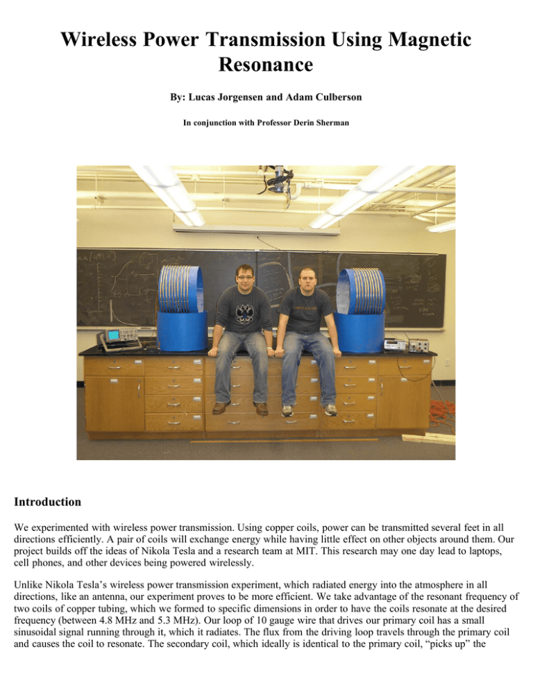
Wireless Power Transmission Using Magnetic Resonance By: Lucas Jorgensen and Adam Culberson In conjunction with Professor Derin Sherman Introduction We experimented with wireless power transmission. Using copper coils, power can be transmitted several feet in all directions efficiently. A pair of coils will exchange energy while having little effect on other objects around them. Our project builds off the ideas of Nikola Tesla and a research team at MIT. This research may one day lead to laptops, cell phones, and other devices being powered wirelessly. Unlike Nikola Tesla’s wireless power transmission experiment, which radiated energy into the atmosphere in all directions, like an antenna, our experiment proves to be more efficient. We take advantage of the resonant frequency of two coils of copper tubing, which we formed to specific dimensions in order to have the coils resonate at the desired frequency (between 4.8 MHz and 5.3 MHz). Our loop of 10 gauge wire that drives our primary coil has a small sinusoidal signal running through it, which it radiates. The flux from the driving loop travels through the primary coil and causes the coil to resonate. The secondary coil, which ideally is identical to the primary coil, “picks up” the vibrations from the primary coil and resonates. This interaction between the two coils, known as coupling, allows the primary coil to drive the secondary coil from a distance. Because the frequency they are vibrating at is the natural, desired frequency, it takes less energy to drive the secondary coil at the resonant "natural" frequency. The magnetic flux from the secondary coil induces a current in the receiving loop of 10 gauge wire, which drives a load.The amount of power that the coils transmit decays exponentially as they are moved further apart. As the primary coil resonates it emits evanescent waves that cause the secondary coil to resonate. As with all evanescent waves, the amplitude of the waves emitted by the primary coil diminish exponentially. This explains why the power generated by the secondary coil in the receiving loop decays exponentially as the two coils move further apart. The reason that these frequencies(4.8-5.3 Mhz) were chosen is that very few household objects interact magnetically at these frequencies. Also, organic matter, such as humans, do not interact at these frequencies. This means that there will be no detrimental effects on people or objects in the vicinity of this setup. Frequencies around 5 Mhz are also good because those frequencies, when coupled with the fact that the wave experiences exponential decay, provide us with an adequate midrange transmitter. Short-range transmitters already exist in applications such as electronic toothbrushes which use transformers to accomplish the power transmission. This is the first mid-range efficient transmission method. What Is Magnetic Resonance? Magnetic resonance occurs when magnetic waves of certain frequencies are absorbed by an object, causing that object to resonate. The frequency absorbed by an object which causes that object to resonate is dependent on many variables, including molecular structure, shape, and size/length of the object. In our experiment we have a primary coil emitting evanescent, magnetic waves that a secondary coil absorbs. Evanescent waves are different from ordinary waves, because evanescent waves oscillate in time, but diminish over distance (This links to an example of evanescent waves) . Assuming the coils are of the same size, shape, and mass, at a certain frequency (the resonant frequency) the primary coil will resonate and cause the secondary coil to resonate as well. The Experimental Setup Our experiment had six basic parts: the oscillator, broadcast antenna, sending coil, receiving coil, pick-up antnna, and load. All of these except the oscillator and load are illustrated in Image 1 below. The broadcast antenna, illustrated by object A, is a single loop of insulated copper wire. The sending coil and receiving coil are illustrated by objects B and C respectively.These coils of copper tubing are made to be exactly the same so they resonate at the same frequency. The pick-up antenna is object D in Image 1 and is connected in series to a load. The resonant frequency of our coils, at which we get the most power, varies with the distance between the coils. Due to this we chose to use a frequency generator so that we could adjust the frequency as needed. Several oscillators were built to generate certain frequencies, but due to the varying nature of our resonant frequency, the frequency generator was used. A frequency generator outputs a signal of the same frequency as the resonant frequency of our copper coils, because we can output maximum power at this frequency. The signal generated is put into our driving loop of 10 gauge wire. The loop is just smaller than our primary coil (approximately 55.5 cm in diameter). The AC current in the driving loop causes the loop of wire to behave like a dipole. The driving loop is positioned parallel to the primary coil, as close as possible. The flux generated by the driving loop through the primary coil causes the coil to resonate. It is important to realize that the driving loop does not make the secondary loop resonate directly. The evanescent waves emitted by the primary coil causes the secondary coil to resonate, because the coils are of the same shape, size, and mass (or close to identical). Both the primary coil and the secondary coil are made of copper tubing that is 1/4 inch inner diameter (3/8 inch outer diameter). The coils use 60 feet of tubing each, and have about 10 turns (57.5 cm in diameter). At this point the two coils are parallel to each other and resonating, using only enough power to make the driving loop “drive” the first coil. The distance between the primary and secondary coils determines the magnitude of power that is transmitted. The power exponentially decays as the coils are moved further apart. When the secondary coil vibrates at its resonant frequency, a stronger magnetic field is generated. The receiving loop of 10 gauge wire is situated parallel to the secondary coil, as close as possible. The magnetic flux from the secondary coil induces a current in the receiving loop, which drives a resistive load. Results To find the power output, we measured the voltage across a 25 ohm power resistor at varying distances and orientations. We took a measurement every 25 cm. We found that the resonant frequency changed with distance due to the imperfect match in the resonant frequencies of our coils. The frequency was then adjusted to find the maximum output voltage at every measurement. Graph 1 The above graph shows the reduction in power as the distance between the coils increases. At a distance of 3.25 meters it was difficult to discern the signal from the noise. Graph 2 The linearity in this logarithmic plot shows the exponential decay from our evanescent waves. Graph 3 We then made the coils perpendicular to each other to reduce the coupling of the two antenna. We observed a similar reduction in power as the distance between the coils increased. The effective range of the power transmission was still 3.25 meters. Graph 4 The linearity in this logarithmic plot shows the exponential decay still exists even in the perpendicular case. This is a link to the data sheets used to create the above graphs References Hsiu C. Han, 1996. Plasma. http://www.ee.iastate.edu/~hsiu/movies/plasma.mov (February 24, 2008) Andre Kurs,Aristeidis Karalis,Robert Moffatt, J. D. Joannopoulos, Peter Fisher, Marin Soljacic. 2008. Wireless Power Transfer via Strongly Coupled Magnetic Resonances. Science. http://www.sciencemag.org/cgi/rapidpdf/1143254?ijkey=94ff.Ay4jRMqU&keytype=ref&siteid=sci (accessed February 24, 2008).


