Massachusetts Institute of Technology
advertisement
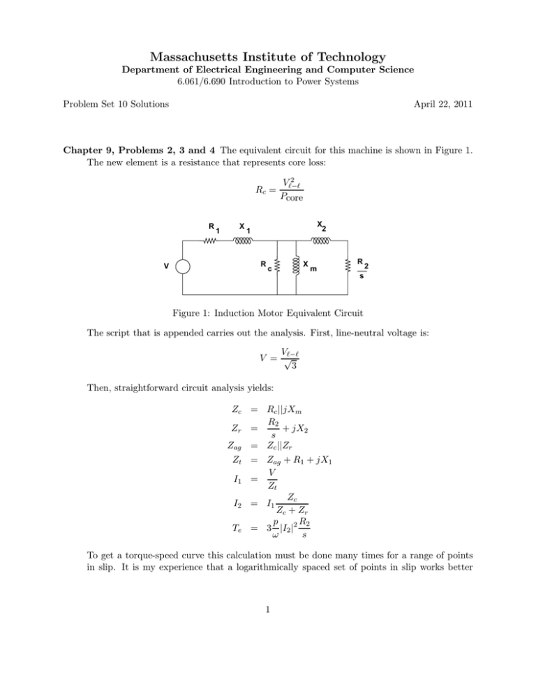
Massachusetts Institute of Technology Department of Electrical Engineering and Computer Science 6.061/6.690 Introduction to Power Systems Problem Set 10 Solutions April 22, 2011 Chapter 9, Problems 2, 3 and 4 The equivalent circuit for this machine is shown in Figure 1. The new element is a resistance that represents core loss: Rc = R V 1 X 2 Vℓ−ℓ Pcore X 2 1 R c X R m 2 s Figure 1: Induction Motor Equivalent Circuit The script that is appended carries out the analysis. First, line-neutral voltage is: Vℓ−ℓ V = √ 3 Then, straightforward circuit analysis yields: Zc = Rc ||jXm R2 + jX2 Zr = s Zag = Zc ||Zr Zt = Zag + R1 + jX1 V I1 = Zt Zc I2 = I1 Zc + Zr R2 p Te = 3 |I2 |2 ω s To get a torque-speed curve this calculation must be done many times for a range of points in slip. It is my experience that a logarithmically spaced set of points in slip works better 1 R’ 1 X 2 X’ 1 + R V’ 2 s − Figure 2: Induction Motor Equivalent Circuit since it can yield a lot of points for small values of slip and fewer points for high slip where things are not very interesting. Generally we would want to plot things against speed: f RP M = 60 (1 − s) p Current vs. Speed and Torque vs. Speed are displayed in Figures 3 and 4 respectively. The lazy way of getting peak torque is to use MATLAB’s max() function. But if you want to use the formula in the book, we first construct the simplified equivalent circuit, shown in Figure 2 The revised elements in this circuit are: Xm R1 + j ∗ X1 + jXm = R1 + j ∗ X1 ||jXm R1 X1 Xm = R12 + (X1 + Xm )2 Xm R12 + X1 Xm (X1 + Xm ) = R12 + (X1 + Xm )2 V ′ = |V R1′ + jX1′ R1′ X1′ Then peak torque is, from the un-numbered expression on page 296 of the book: Tmax = 3p |V ′ |2 � 2 ω R′ + (R′ )2 + (X ′ + X )2 2 1 1 1 Note that I have left off the impact of the core resistance in the expressions above, due to sloth. However, numerically I did calculate the equivalent circuit elemente with the core effect included. The results produced by the script are pretty close together, vindicating my laziness. Max Torque = 246.343 Classical Calc = 246.623 Classical with complete params = 246.345 2 Problem 1 140 120 Amperes, RMS 100 80 60 40 20 0 0 200 400 600 800 1000 RPM 1200 1400 1600 1800 Figure 3: Induction Motor Current vs. Speed Problem 1 250 200 N−m 150 100 50 0 0 200 400 600 800 1000 RPM 1200 1400 1600 1800 Figure 4: Induction Motor Torque vs. Speed 3 Script for Problem 1: % Problem Set 10, Problem 1 % parameters Vll = 480; p = 2; f = 60; r1 = .2; r2 = .24; x1 = 1; x2 = 1.2; xm = 50; Pc = 400; Pf = 75; rc = Vll^2/Pc; V = Vll/sqrt(3); om = 2*pi*f; % core resistance % line-neutral voltage Vp = V*xm/abs(r1+j*(xm+x1)); % for max torque calc rp =(r1*x1*xm^2)/(r1^2+(x1+xm)^2); xp =(xm*r1^2+x1*xm*(x1+xm))/(r1^2+(x1+xm)^2); zc = j*xm*rc/(j*xm+rc); % core branch impedance s = logspace(-3,0,500); % slip zr = j*x2 + r2 ./ s; zag = zr .*zc ./(zr+zc); % rotor impedance % air gap impedance zt = r1+j*x1 + zag; % terminal impedance It = V ./ zt; % terminal current I2 = It .* zc ./(zc + zr); % secondary current Te = 3*(p/om) * r2 .* abs(I2) .^2 ./ s; % torque omm = (om/p) .* (1 - s); rpm = (30/pi) .* omm; % mechanical speed % in RPM Tp1 = max(Te); % first cut at max torque figure(1) plot(rpm, Te) 4 title(’ Problem 1’) ylabel(’N-m’) xlabel(’RPM’) % alternate to max torque 1: Tp2 = (1.5*p/om) *abs(Vp)^2/(rp+sqrt(rp^2 + (xp+x2)^2)); fprintf(’Max Torque = %g\n’, Tp1) fprintf(’Classical Calc = %g\n’, Tp2) % third attempt at max torque zs = (r1+j*x1)*zc/(r1+j*x1+zc); rpa = real(zs); xpa = imag(zs); vpa =abs(V*zc/(r1+j*x1+zc)); Tp3 = (1.5*p/om) *abs(vpa)^2/(rpa+sqrt(rpa^2 + (xpa+x2)^2)); fprintf(’Classical with complete params = %g\n’, Tp3) % plot of terminal current: figure(2) plot(rpm, abs(It)) title(’Problem 1’) ylabel(’Amperes, RMS’) Problem 2 This problem has several parts and starts out very much like Problem 1. In fact the machine is the same motor as in Problem 1, re-wound for a different terminal voltage. All of the calculations for this problem and the next one are carried out in the attached script. 1. Torque vs. speed is plotted in Figure 5 2. Current vs. speed is plotted in Figure 6. 3. Breakdown torque is calculated using the max() function in Matlab: Part 3: Max Torque = 242.723 4. When running light, the motor is delivering only friction and windage, assumed to be, somewhat improbably, constant. To find that point we employ a two-step strategy. • First, find two adjacent points in slip for which the net shaft power (that is power minus friction and windage) are, respectively, negative and then positive. This means the actual operating point is somewhere between the two points. • Use linear interpolation (See Figure 7 to estimate the point in slip where the motor is delivering the right power. the better estimate for slip is: sz = s1 + (s2 − s1 ) 5 −P1 P2 − P1 Problem 2 250 200 N−m 150 100 50 0 0 200 400 600 800 1000 RPM 1200 1400 1600 1800 Figure 5: Induction Motor Torque vs. Speed Problem 2 100 90 80 Amperes, RMS 70 60 50 40 30 20 10 0 0 200 400 600 800 1000 RPM 1200 1400 1600 1800 Figure 6: Induction Motor Current vs. Speed 6 P2 s1 s 2 P1 Sz Figure 7: Linear Interpolation Note this is not a perfect estimate, but it appears to give a fairly close estimate of the correct value of slip. Using that interpolated value of slip, motor operation is re-evaluated at the one point and we find: Part 4: Running Light: Speed = 1799.85 RPM Real Power = 476.681 Reactive Power = 4697.06 Current = 4.54297 A 5. Locked rotor (or ’blocked rotor’) is easy since we know the speed. The equivalent circuit is evaluated and the magnitude of impedance dictates the voltage that needs to be used. The rest is straightforward. Note that this test actually produces relatively little torque: Part 5: Locked Rotor Test Current = 22.4 A Voltage = 78.756 V Real Power = 994.037 W Reactive Power = 5198.21 VAR Torque = 2.99466 N-m 6. We actually have all we need for the calculation of efficiency and power factor: all that is required is to identify which values of slip correspond with the lower and upper bounds of power. Then we can calculate efficiency (Power out/power in) and power factor (power in/apparent power) over that range of slips and do a cross-plot. This is shown in Figure 8. 7. This last part corresponds to volts-per-Hz control of the machine. With only a few curves to plot we can calculate them one by one and then plot them on a static plot window using ’hold’. There are a couple of things to recognize are important: • Voltage varies with speed, so it is important to schedule the right voltage • Reactances are functions of frequency, so we simply multiply the reactances X1 , X2 and Xm by the ratio of frequency to base frequency (60 Hz). The torque-speed curves are shown in Figure 9 The script that was used to generate all of this stuff was also used for Problem 3 and will appear after that problem. 7 Problem 2, Part 6 1 Efficiency 0.9 0.8 0.7 0 0.2 0.4 0.6 0.8 1 1.2 1.4 1.6 1.8 2 4 x 10 Power Factor 1 0.8 0.6 0.4 0.2 0 0.2 0.4 0.6 0.8 1 1.2 Output Power 1.4 1.6 1.8 2 4 x 10 Figure 8: Efficiency and Power Factor vs. Load Problem 2, Part 7 250 200 N−m 150 100 50 0 0 500 1000 1500 RPM 2000 2500 3000 Figure 9: Torque vs. Speed, Volts/Hz Control 8 4 3 Problem 3 x 10 Power In Power Out 2.5 Watts 2 1.5 1 0.5 0 0 500 1000 1500 RPM 2000 2500 3000 Figure 10: Volts per Hz. Input and Output Power Problem 3: Volts/Hz Operation The procedure for this problem is very similar to what was used in the Problem 2 to find the ’running light’ point and, of course, the last part of that problem. It is all in the script. For each of several points in frequency a torque vs. speed curve is run, then the actual point in slip is identified by: • finding two points that straddle the required torque, • linear interpolation is used to find the slip appropriate for that speed, • The model is run again for the single point, and real and reactive power in and power out are identified And then efficiency and power factor are calculated. The results are shown in Figures 10 and 11. 9 Problem 3 1 0.9 0.8 per−unit 0.7 0.6 0.5 0.4 0.3 0.2 Efficiency Power Factor 0 500 1000 1500 RPM 2000 2500 3000 Figure 11: Volts per Hz. Efficiency and Power Factor vs. Speed 10 Script for Problems 2 and 3: % Problem Set 10, Problems 2 and 3 % parameters Vll = 600; p = 2; f = 60; r1 = .3; r2 = .375; x1 = 1.6; x2 = 1.9; xm = 75; Pc = 400; Pf = 75; Pmin = 933; Pmax = 18650; rc = Vll^2/Pc; % core resistance V = Vll/sqrt(3); % line-neutral voltage % frequency in radians/second om = 2*pi*f; % core branch impedance zc = j*xm*rc/(j*xm+rc); s = logspace(-4,0,500); % slip range % rotor impedance zr = j*x2 + r2 ./ s; zag = zr .*zc ./(zr+zc); % air gap impedance % terminal impedance zt = r1+j*x1 + zag; % terminal current It = V ./ zt; % secondary current I2 = It .* zc ./(zc + zr); Te = 3*(p/om) * r2 .* abs(I2) .^2 ./ s; % torque Pm = (om/p) .* Te .* (1-s) - Pf; % shaft power produced % input power Pin = real(3 .* V .* conj(It)); % input reactive power Qin = imag(3 .* V .* conj(It)); % mechanical speed omm = (om/p) .* (1 - s); % in RPM rpm = (30/pi) .* omm; Tp1 = max(Te); figure(1) plot(rpm, Te) title(’ Problem 2’) ylabel(’N-m’) xlabel(’RPM’) grid on % plot of terminal current: figure(2) 11 plot(rpm, abs(It)) title(’Problem 2’) ylabel(’Amperes, RMS’) xlabel(’RPM’) grid on fprintf(’Part 3: Max Torque = %g\n’, Tp1) figure(3) plot(rpm, Pm) title(’Problem 2’) ylabel(’Output Power, Watts’) xlabel(’RPM’) grid on % running light: it makes only friction and windage, Pf % search over s to find light operating point for k = 1:length(s)-1 if Pm(k) < 0 & Pm(k+1) >0, kz = k; break; end end % now do linear interpolation sz = s(kz) - (s(kz+1)-s(kz)) * Pm(kz)/(Pm(kz+1)-Pm(kz)); zrl = j*x2 + r2 / sz; % rotor impedance zagl = zrl *zc /(zrl+zc); % air gap impedance ztl = r1+j*x1 + zagl; % terminal impedance Itl = V / ztl; I2l = Itl * zc /(zc + zrl); % terminal current % secondary current Pem = 3 * (r2/sz) * abs(I2l) .^2 - Pf; % net shaft power Pl = real(3*V*conj(Itl)); Ql = imag(3*V*conj(Itl)); Nl = (60*f/p)*(1-sz); fprintf(’Part 4: Running Light: Speed = %g RPM\n’, Nl) fprintf(’Real Power = %g Reactive Power = %g\n’, Pl, Ql) fprintf(’Current = %g A\n’, abs(Itl)) % blocked rotor test 12 Ilrm = 22.4; % test current magnitude zrl = j*x2+r2; zagl = zrl * zc / (zrl + zc); ztl = r1 + j*x1 + zagl; Vlr = abs(Ilrm * ztl); Ilr = Vlr / ztl; % actual test current I2lr = Ilr * zc/(zc+zrl); % rotor current Plr = real(3*Vlr*conj(Ilr)); Qlr = imag(3*Vlr*conj(Ilr)); Tlr = 3*(p/om)*r2*abs(Ilr)^2; fprintf(’Part 5: Locked Rotor Test\n’) fprintf(’Current = %g A Voltage = %g V\n’, abs(Ilr), Vlr) fprintf(’Real Power = %g W Reactive Power = %g VAR\n’, Plr, Qlr) fprintf(’Torque = %g N-m\n’, Tlr) % part 6: over some range of operation % minimum for k = 1:length(s)-1 if Pm(k) < Pmin & Pm(k+1) >Pmin, kmin = k; break; end end for k = 1:length(s)-1 if Pm(k) < Pmax & Pm(k+1) >Pmax, kmax = k; break; end end P_out = Pm(kmin:kmax); P_in = Pin(kmin:kmax); Q_in = Qin(kmin:kmax); VA_in = sqrt(P_in .^2 + Q_in .^2); Eff = P_out ./ P_in; PFACT = P_in ./ VA_in; figure(4) subplot 211 plot(P_out, Eff) title(’Problem 2, Part 6’) ylabel(’Efficiency’) grid on subplot 212 13 plot(P_out, PFACT) ylabel(’Power Factor’) xlabel(’Output Power’) grid on % part 7: Adjustable voltage F = [20 40 60 80 100]; vr = [2/6 4/6 1 1 1]; f0 = 60; figure(5) clf hold on for k = 1:length(F) f = F(k); om = 2*pi*f; % frequency in radians/second zc = j*(f/f0)*xm*rc/(j*(f/f0)*xm+rc); % core branch impedance s = logspace(-4,0,500); % slip range zr = j*(f/f0)*x2 + r2 ./ s; % rotor impedance zag = zr .*zc ./(zr+zc); % air gap impedance zt = r1+j*(f/f0)*x1 + zag; % terminal impedance It = vr(k)*V ./ zt; % terminal current I2 = It .* zc ./(zc + zr); % secondary current Te = 3*(p/om) * r2 .* abs(I2) .^2 ./ s;% torque N = (60*f/p) .* (1-s); plot(N, Te) end hold off title(’Problem 2, Part 7’) ylabel(’N-m’) xlabel(’RPM’) grid on % Problem 3: continuation of adjustable voltage T_l = 100; % constant load characteristic F = 15:5:150; % this frequency range V_ph = zeros(size(F)); P_in = zeros(size(F)); % scratch space P_out = zeros(size(F)); PFact = zeros(size(F)); Efficiency = zeros(size(F)); Nr = zeros(size(F)); for k = 1:length(F) % set volts/Hz if f<60 14 V_ph(k) = V*F(k)/60; else V_ph(k) = V; end end % now do the calculation: should be familiar by now for k = 1:length(F) f = F(k); Vt = V_ph(k); om = 2*pi*f; % frequency in radians/second zc = j*(f/f0)*xm*rc/(j*(f/f0)*xm+rc); % core branch impedance % slip range s = logspace(-4,0,500); zr = j*(f/f0)*x2 + r2 ./ s; % rotor impedance zag = zr .*zc ./(zr+zc); % air gap impedance zt = r1+j*(f/f0)*x1 + zag; % terminal impedance It = Vt ./ zt; % terminal current I2 = It .* zc ./(zc + zr); % secondary current T_em = 3 * (p/om) .*r2 .* abs(I2) .^2 ./ s; % shaft torque % now we find the slip for the load torque if max(T_em) < T_l % all done kmax = k-1; break; else for kk = 1:length(s)-1 if T_em(kk) < T_l && T_em(kk+1) > T_l, kr = kk; break; end end % improve our guess by linear interpolation sr = s(kr) + (s(kr+1)-s(kr)) * (T_l - T_em(kr))/(T_em(kr+1)-T_em(kr)); % now do the calculation at this point zrr = j*(f/f0)*x2 + r2 / sr; % rotor impedance zagr = zrr *zc /(zrr+zc); % air gap impedance ztr = r1+j*(f/f0)*x1 + zagr; % terminal impedance Itr = Vt / ztr; % terminal current I2r = Itr * zc /(zc + zrr); % secondary current P_out(k) = 3 * (r2/sr) * abs(I2r) .^2;% - Pf*(f/f0)^3; % net shaft power P_in(k) = real(3*Vt*conj(Itr)); % real power in Q_in(k) = imag(3*Vt*conj(Itr)); % real power out Nr(k) = (60*f/p)*(1-sr); % rotational speed VA = sqrt(P_in(k)^2 + Q_in(k)^2); 15 Is jX 1 jX2 I2 + V S + j Xm V 2 − − N :N S R + V R s − Figure 12: Doubly Fed Induction Machine Equivalent Circuit Efficiency(k) = P_out(k)/P_in(k); PFact(k) = P_in(k)/VA; end end % now need to clip all of these to match actual capacity Nrp = Nr(1:kmax); P_inp = P_in(1:kmax); P_outp = P_out(1:kmax); PFactp = PFact(1:kmax); Effp = Efficiency(1:kmax); figure(6) plot(Nrp, P_inp, Nrp, P_outp); title(’Problem 3’) ylabel(’Watts’) xlabel(’RPM’) legend(’Power In’, ’Power Out’) grid on figure(7) plot(Nrp, Effp, Nrp, PFactp) title(’Problem 3’) ylabel(’per-unit’) xlabel(’RPM’) legend(’Efficiency’, ’Power Factor’) grid on Problem 4: DFM as Wind Generator If we take the liberty of ignoring resistances, the DFM can be represented as shown in 12 Noting the sign convention here, we know that power input to the rotor is related to power output from the stator by: PR = sPS Then, since mechanical power into the machine must be equal to the difference beween these: 16 PM = PS − PR We can find power out of the stator of the machine PS = PM 1−s If, as stated in the problem description, the system side of the bidirectional converter is interacting with the power system at unity power factor, meaning zero reactive power, all reactive power to the system must be supplied by the stator, so that, using pf as power factor: � � 1 −1 QS = PM pf 2 Real and reactive power are: PS + jQS = 3V I ∗ which means that terminal current (in this case out of the stator is: IS = PS = jQS 3V Keeping within the system frequency part of the equivalent circuit, we can find voltage across the magnetizing branch: Vm = V + jX1 IS The resulting current through the magnetizing branch is: Im = Vm jXm and since I2 = IS + Im , V2 = Vm + jX2 I2 Real and reactive power into the rotor, apparent from the stator frame, are: P2 + jQ2 = 2V2 I2∗ And then real and reactive power at the terminals of the rotor (slip rings) are: PR = sP2 QR = |s|Q2 Alternatively, rotor voltage and current can be seen to be modified by the stator to rotor transformer ratio and, in the case of voltage, slip: VR = IR = 17 NR sV2 NS NS I2 NR 6 Rotor Power, Watts 1.5 Problem 5 x 10 1 0.5 0 −0.5 −1 1200 1400 1600 1800 2000 2200 2400 1400 1600 1800 RPM 2000 2200 2400 8 2 x 10 VARs 1.5 1 0.5 0 1200 Figure 13: Real and Reactive Power into Slip Rings of DFM There is one subtlety here: for negative values of slip, where rotor power is negative (that is real power is coming out of the rotor), the phase sequence on the rotor reverses, so that the reactive component of current changes sign (with respect to positive slip). This gives an extra sign change to reactive power, which is why it is multiplied by |s|. The calculations described here are carried out in the attached script and result in: Problem 4 +30 percent slip Rotor Real Power = 1.02857e+06 W Reactive = 1.54624e+08 VARs -30 percent slip Rotor Real Power = -553846 W Reactive = 6.26373e+07 VARs Problem 5: More DFM as Wind Turbine There is relatively little new in this, beyond what was done in Problem 4, aside from finding rotor speed, which is: Nm = 60f (1 − s) p The calculations described above are carried out for a collection of points in slip and then cross-plotted against speed in RPM, and the results are shown in Figure 13 Matlab Code for Problems 4 and 5 18 % Problem Set 10, Problems 4 and 5 % data f = 60; p = 2; om = 2*pi*f; Pm = 2.4e6; pf = 0.8; Vs = 690/sqrt(3); N = 3; % % % % % % system frequency pole pairs radians per second turbine power power factor stator voltage X1 = om*(.0035+.00175); % machine reactances X2 = om*(.0315+.01575)/N^2; % referred to the stator Xm = om*.0104/N; s = .3:(-.01):-.3; Ps = Pm ./ (1-s); Q0 = Pm *(1/pf^2 - 1); % this is the range of speeds % stator OUTPUT power % reactive power Qs = Q0 .* ones(size(Ps)); % so they match Is = (Ps - j .* Qs) ./ (3*Vs); Vm Im I2 V2 = = = = Vs Vm Is Vm + j*X1 .* Is; ./(j*Xm); + Im; + j*X2 .* I2; % terminal current % magnetizing branch voltage % rotor side current % rotor voltage P2 = 3 .* real(V2 .* conj(I2)); Q2 = 3 .* imag(V2 .* conj(I2)); Pr = s .* P2; Qr = abs(s) .* Q2; % alternate calc Ir = I2 ./ N; Vr = V2 .* N .* s; Pra = 3 .* real(Vr .* conj(Ir)); Qra = 3 .* imag(Vr .* conj(Ir)); % Problem 4 Pr1 = Pr(1); 19 Pr2 = Pr(length(Pr)); Qr1 = Qr(1); Qr2 = Qr(length(Pr)); % check Pr1a = Pra(1); Pr2a = Pra(length(Pr)); Qr1a = Qra(1); Qr2a = Qra(length(Pr)); fprintf(’Problem 4\n’) fprintf(’+30 percent slip\n’) fprintf(’Rotor Real Power = %g fprintf(’-30 percent slip\n’) fprintf(’Rotor Real Power = %g fprintf(’Check:\n’) fprintf(’+30 percent slip\n’) fprintf(’Rotor Real Power = %g fprintf(’-30 percent slip\n’) fprintf(’Rotor Real Power = %g W Reactive = %g VARs\n’, Pr1, Qr1) W Reactive = %g VARs\n’, Pr2, Qr2) W Reactive = %g VARs\n’, Pr1a, Qr1a) W Reactive = %g VARs\n’, Pr2a, Qr2a) % Problem 5 RPM = (60*f/p) .* (1-s); figure(1) subplot 211 plot(RPM, Pr) title(’Problem 5’) ylabel(’Rotor Power, Watts’) grid on subplot 212 plot(RPM, Qr) ylabel(’VARs’) xlabel(’RPM’) grid on 20 MIT OpenCourseWare http://ocw.mit.edu 6.061 / 6.690 Introduction to Electric Power Systems Spring 2011 For information about citing these materials or our Terms of Use, visit: http://ocw.mit.edu/terms.

