CHAPTER 1: INTRODUCTION
advertisement
CHAPTER 1: INTRODUCTION
1.1 SCOPE AND CONTENT
Communications and sensing systems are ubiquitous. They are found in military, industrial,
medical, consumer, and scientific applications employing radio frequency, infrared, visible, and
shorter wavelengths. Even acoustic systems operate under similar principles. Communications
examples range from optical fiber or satellite systems to wireless radio. Radio astronomy, radar,
lidar, and sonar systems probe the environment and have counterparts in analytical instruments
and memory systems used for a wide variety of purposes.
HUMAN
PROCESSOR
B
A
TRANSDUCER
C
Radio
Optical, Infrared
Acoustic, other
Electromagnetic
Environment
D
HUMAN
G
PROCESSOR
F
TRANSDUCER
E
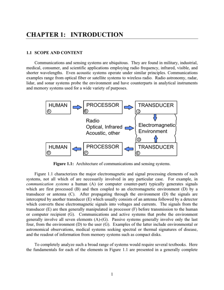
Figure 1.1: Architecture of communications and sensing systems.
Figure 1.1 characterizes the major electromagnetic and signal processing elements of such
systems, not all which of are necessarily involved in any particular case. For example, in
communication systems a human (A) (or computer counter-part) typically generates signals
which are first processed (B) and then coupled to an electromagnetic environment (D) by a
transducer or antenna (C). After propagating through the environment (D) the signals are
intercepted by another transducer (E) which usually consists of an antenna followed by a detector
which converts these electromagnetic signals into voltages and currents. The signals from the
transducer (E) are then generally manipulated in processor (F) before transmission to the human
or computer recipient (G). Communications and active systems that probe the environment
generally involve all seven elements (A)-(G). Passive systems generally involve only the last
four, from the environment (D) to the user (G). Examples of the latter include environmental or
astronomical observations, medical systems seeking spectral or thermal signatures of disease,
and the readout of information from memory systems such as compact disks.
To completely analyze such a broad range of systems would require several textbooks. Here
the fundamentals for each of the elements in Figure 1.1 are presented in a generally complete
1
way but, for efficiency, only few of their possible combinations are presented in any detail. For
example, the probability of symbol detection error is analyzed for communications systems, but
this analysis is not repeated for other systems. It is hoped that readers of this book will acquire
sufficient understanding of the elements of Figure 1.1 to be able to conceive, design, and analyze
a wide variety of electromagnetic signal-based systems by combining these elements
appropriately.
The chapters of this book can be divided into three groups. First Chapter 1 defines the basic
notation and surveys briefly some of the basic notation fundamental to signal processing and
electromagnetic waves.
The second group of chapters focuses on the fundamental elements of communications and
sensing systems. Chapter 2 discusses basic noise processes and the devices used for detection of
radio, infrared, and visible signals, including those first-stage signal processing operations that
yield the desired signal, energy, or power spectral density estimates. Chapter 3 then discusses
the transducers and antennas that link these detectors to the electromagnetic environment,
including wire antennas, apertures, simple optics, common propagation phenomena, and how the
transmitting and receiving properties of systems are related in a simple way.
The third group of chapters deals with complete systems applied to communications
(Chapter 4) and both active and passive sensing (Chapter 5). Estimation techniques for both
sensing and communication systems are then discussed separately in Chapter 6.
1.2 MATHEMATICAL NOTATION
Because physical signals are generally analog, we rely in this text more heavily on
continuous functions and operators than on discrete signals and the z transform. Physical signals
in time or space are generally represented by lower case letters followed by their arguments in
parentheses, whereas their transforms are generally represented by capital letters, again followed
by their arguments in parentheses. Complex quantities are generally indicated by underbars. For
example, the Fourier transform relating a voltage pulse v(t) to its spectrum V(f) is:
f
V f ³ v t e j2Sft dt > volts Hz
f
voltsec @
(1.2.1)
f
vt
³ V f e j2Sft df
f
> volts @
v ( t ) l V (f )
(1.2.2)
(1.2.3)
where frequency is generally represented by f(Hz) or Z 2Sf (radians/ second). We abbreviate
this Fourier relationship as: v(t) l V(f ). These relations apply for pulses of finite energy, i.e.:
2
f
³ v(t) 2 dt f
(1.2.4)
f
2
The energy spectrum S f V f and has units ª¬ volts 2 Hz º¼ for the case where v(t) has
units [volts]. This energy density spectrum is the Fourier transform of the voltage
autocorrelation function R(W), where:
f
V f 2
S f l R W '
³f v t v t W dt
ª v2 secº or >J@ , etc.
¬
¼
(1.2.5)
Parseval’s theorem, which says that the integral of power over time equals the integral of energy
spectral density S(f) over frequency, follows easily from Equation (1.2.5) and the definition of a
Fourier transform (1.2.2) for t = 0:
f
R (0)
f
³ v2 t dt = ³ Sf df .
f
(1.2.6)
f
These relationships for analytic pulse signals can be represented compactly by the following
notation:
vt l Vf p
p
(1.2.7)
2
R W l Vf ' Sf The single-headed arrows pointing downward indicate that the transformations from v(t) to R(W),
2
and from Vf to Vf are irreversible. The units of these quantities depends on the units
associated with v(t). For example, if v(t) represents volts as a function of time, then the units in
clockwise order in (1.2.7) for these four quantities are: volts, volts/Hz, (volts/Hz)2, and volts2
seconds. If this voltage v(t) is across a 1-ohm resistor, then we can associate the autocorrelation
function R(W) with the units Joules, and the energy density spectrum S(f) with the units
Joules/Hz.
Another important operator is convolution, represented by an asterisk, where:
3
f
³ a W b t-W dW = c t .
a(t) b(t) '
(1.2.8)
f
Note that a unit impulse convolved with any function yields the original function, where we
define the unit impulse G(t) as a function which is zero for |t| > 0, and has an integral of value
unity.
Periodic signals with finite energy in each period T can be reversibly characterized by their
Fourier series and irreversibly characterized by their autocorrelation function R(W) and its Fourier
transform, the energy density spectrum )m. These are related as suggested in Equation 1.2.9
v t l Vm (volts)
p
p
(1.2.9)
R W l )m watts Hz
-1
or S(f ) (Joules)
The Fourier series Vm can be simply computed from the original waveform v(t) as:
T 2
Vm
T
1
³
v(t)e jm2Sfo t dt
(1.2.10)
T 2
where T equals fo-1 and:
f
v(t)
¦
Vm <e jm2 Sfo t
(1.2.11)
m f
T 2
R(W)
v(t)v (t W)dt
³
)m
Vm
¦
2
Vm e jm2Sfo W
(1.2.12)
m f
T 2
2
f
T 2
T
1
³
R(W)e jm2Sfo WdW
(1.2.13)
T 2
Random signals x(t) can often be characterized by their autocorrelation function:
Ix W E > x t x t W@.
(1.2.14)
Such signals are called “wide-sense stationary” stochastic signals. For the special case where the
signal x(t) is the voltage across a 1-ohm resistor, the autocorrelation function I(W) for W = 0 may
4
be regarded as the average power dissipated in the resistor, and the Fourier transform of the
autocorrelation function can be regarded as the power spectral density )f (watts/Hz) where:
vt ?
l
p
p
(1.2.15)
Iv W l ) f In many cases we shall encounter Gaussian noise n(t), where the probability distribution of
n is:
P ^n`
1
n V 2
e V 2S
2
(1.2.16)
f
> @ ³f pn n 2dn
E n2
V2 .
(1.2.17)
Band-limited Gaussian white noise, which is defined as having a uniform power spectral density
)(f) over a band of width B (Hz), can be characterized by the noise power spectral density No,
where:
E > n 2 @ V2
(1.2.18)
NoB
Signal or wave powers are often characterized in terms of decibels, where if a signal
increases its power of P1 to P2 we say there has been a gain of:
dB gain ' 10 log10 P2 P1 (1.2.19)
Thus an amplifier having power output equal to the power input exhibits 0 dB gain, where power
gains of a factor of 10 or 100 correspond to 10 dB and 20 dB, respectively.
1.3 ELECTROMAGNETIC NOTATION
We characterize electromagnetic phenomena in terms of the electric field E (volts / meter)
and magnetic field H (amperes/meter), where these fields have both a magnitude and direction
at each point in space and time.
We represent the electric displacement by
2
D (coulombs / meter ) , where for simple media D H E and the permittivity H for vacuum is
Ho
8.854 u 10
B Tesla
12
farads / meter ; F/m.
Weber m
2
We represent the magnetic flux density by
10 Gauss , where for simple media B P H and the permeability P for
4
5
vacuum is P o 4S u 107 henries/meter; H/m. The electric current density is represented by
J(amperes / meter 2 ; A / m 2 ) and the electric charge density by U(coloumbs/meter3; C/m3).
This text uses SI (mks) units throughout, in which case Maxwell’s equations become:
wB
wt
uE
uH
J
(1.3.1)
wD
wt
(1.3.2)
xD U
(1.3.3)
xB 0
(1.3.4)
' x̂ w wx ŷ w wy ẑ w wz
(1.3.5)
where x,
ˆ y,
ˆ and zˆ are unit vectors in Cartesian coordinates.
In general these field quantities are functions of both space and time and can be represented
in different ways. For example, the x component of a monochromatic electric field at frequency
Z and position r can be represented as:
E x r, t ^
Re E x r e j( Zt Ix (r))
`
^
Re E x r e jZt
`
(1.3.6)
where the operator Re{ } extracts the real part of its argument, and the phasor can be represented
as:
Ex r E x r e jIx
r
(1.3.7)
In general, we may combine all three vector components of E r, t in a phasor representation
to yield:
E r,t Re ^ E r e jZt `
(1.3.8)
where we note that E r has six numbers associated with it (three vectors, each with magnitude
and phase). The other variables are also expressible as phasors when the signals are
monochromatic.
6
Maxwell’s equations can be therefore rewritten in terms of phasors as:
uE
jZB
uH
jZD J
(1.3.9)
(1.3.10)
xD U
(1.3.11)
xB 0
(1.3.12)
Many waves in communications or sensing systems travel on wires or transmission lines
where they may be characterized in terms of voltages V(z, t) and currents I(z,t) as a function of
position z and time t. Most commonly such signals travel on transverse-electromagnetic-field
(TEM) transmission lines for which the voltage is measured between the two conductors at a
particular position z and the currents I(z,t) in the two wires are equal and opposite at any position
z. Such transmission lines can be characterized by their inductance L per unit length (H/m) and
their capacitance C per unit length (C/m). In general, LC = PH, where PH is a function of the
medium between and around the conductors.
In general such transmission lines satisfy the wave equation:
w2v
wz 2
LC
w2v
wt 2
(1.3.13)
The general wave equation solution is the linear superposition of an arbitrarily shaped forward
moving wave v z t LC and a backward moving wave where:
v z, t v z t
LC v z t
LC (1.3.14)
which leads to:
i z, t C L ª v z t
¬
LC v z t
LC º
¼
(1.3.15)
The instantaneous power at any position z on the transmission line is simply the product of the
voltage v and current i at that point in space and time. The phasor equivalents of equations
(1.3.14) and (1.3.15) are:
V z
V e jkz V e jkz
(1.3.16)
and
7
Iz
Yo ª¬ V e jkz V e jkz º¼
(1.3.17)
where the wave number or propagation constant k
admittance of the transmission line Yo
Zo1
Z LC
Z PH , and the characteristic
C L , and where Zo (ohms) is called the
characteristic impedance of the TEM transmission line.
Waves are also characterized by their wavelength O, where O = c/f and c is the phase
velocity of the electromagnetic waves in that medium.
8

