Recitation 10 - Problems Problem 1 #
advertisement
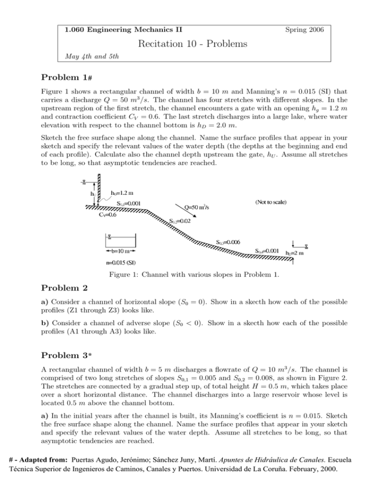
1.060 Engineering Mechanics II Spring 2006 Recitation 10 - Problems May 4th and 5th Problem 1 # Figure 1 shows a rectangular channel of width b = 10 m and Manning’s n = 0.015 (SI) that carries a discharge Q = 50 m3 /s. The channel has four stretches with different slopes. In the upstream region of the first stretch, the channel encounters a gate with an opening hg = 1.2 m and contraction coefficient CV = 0.6. The last stretch discharges into a large lake, where water elevation with respect to the channel bottom is hD = 2.0 m. Sketch the free surface shape along the channel. Name the surface profiles that appear in your sketch and specify the relevant values of the water depth (the depths at the beginning and end of each profile). Calculate also the channel depth upstream the gate, hU . Assume all stretches to be long, so that asymptotic tendencies are reached. Figure 1: Channel with various slopes in Problem 1. Problem 2 a) Consider a channel of horizontal slope (S0 = 0). Show in a skecth how each of the possible profiles (Z1 through Z3) looks like. b) Consider a channel of adverse slope (S0 < 0). Show in a skecth how each of the possible profiles (A1 through A3) looks like. Problem 3 * A rectangular channel of width b = 5 m discharges a flowrate of Q = 10 m3 /s. The channel is comprised of two long stretches of slopes S0,1 = 0.005 and S0,2 = 0.008, as shown in Figure 2. The stretches are connected by a gradual step up, of total height H = 0.5 m, which takes place over a short horizontal distance. The channel discharges into a large reservoir whose level is located 0.5 m above the channel bottom. a) In the initial years after the channel is built, its Manning’s coefficient is n = 0.015. Sketch the free surface shape along the channel. Name the surface profiles that appear in your sketch and specify the relevant values of the water depth. Assume all stretches to be long, so that asymptotic tendencies are reached. Recitation 10-1Apuntes de Hidráulica de Canales. Escuela # - Adapted from: Puertas Agudo, Jerónimo; Sánchez Juny, Martí. Técnica Superior de Ingenieros de Caminos, Canales y Puertos. Universidad de La Coruña. February, 2000. b) Estimate the minimum value of L so that the assumption of long stretches is a good one. c) Due to lack of maintenance, the roughness of the channel increases. Repeat part a with n = 0.03. Again, assume all stretches to be long. Figure 2: Step on channel bottom in Problem 3. Problem 4 * A team of engineers is designing an aqueduct to cross a cliff (see Figure 3). The aqueduct channel will consist of two straight segments, AB and BC, each spanning a horizontal length of 50 m. Segment BC is located above a river and it is not possible to place any pilar along it. For this reason, the engineers want to minimize the weight of water on BC. To this end, they determine that flow must be supercritical along BC. The channel will have a rectangular section of width b = 1 m and sidewall height hSW = 1.15 m. To avoid spills to the cliff, the minimum clearance along the aqueduct is 15 cm (i.e., h ≤ 1 m). The discharge is Q = 1 m3 /s and Manning’s n = 0.015. The channel continues upstream and downstream of the aqueduct with a slope S0,3 = 0.004. Both segments AB and BC are assumed long, so that asymptotic tendencies are reached. The water volume on BC is estimated by approximating the free surface curve to a straight line. a) Determine the range of slopes S0,1 and S0,2 which (1) yield supercritical flow everywhere along BC and (2) satisfy the minimum clearance. b) What are the values of S0,1 and S0,2 that minimize the weight of water on BC? Figure 3: Aqueduct crossing a cliff in Problem 4. 10-2 * - Adapted from: Bonillo Martínez, Juan J.; PuertasRecitation Agudo, Jerónimo; Juncosa Rivera, Ricardo. Problemas de Hidráulica. Escuela Técnica Superior de Ingenieros de Caminos, Canales y Puertos. Universidad de La Coruña. July, 2002.
