Document 13491554
advertisement
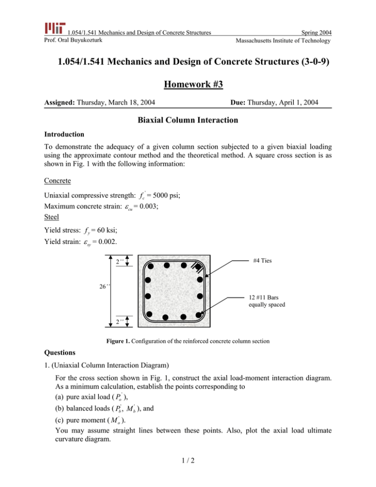
1.054/1.541 Mechanics and Design of Concrete Structures Prof. Oral Buyukozturk Spring 2004 Homework #3 Massachusetts Institute of Technology 1.054/1.541 Mechanics and Design of Concrete Structures (3-0-9) Homework #3 Assigned: Thursday, March 18, 2004 Due: Thursday, April 1, 2004 Biaxial Column Interaction Introduction To demonstrate the adequacy of a given column section subjected to a given biaxial loading using the approximate contour method and the theoretical method. A square cross section is as shown in Fig. 1 with the following information: Concrete ' Uniaxial compressive strength: f c = 5000 psi; Maximum concrete strain: ε cu = 0.003; Steel Yield stress: f y = 60 ksi; Yield strain: ε sy = 0.002. #4 Ties 2’’ 26’’ 12 #11 Bars equally spaced 2’’ Figure 1. Configuration of the reinforced concrete column section Questions 1. (Uniaxial Column Interaction Diagram) For the cross section shown in Fig. 1, construct the axial load-moment interaction diagram. As a minimum calculation, establish the points corresponding to ' (a) pure axial load ( Po ), (b) balanced loads ( Pb' , M b' ), and (c) pure moment ( M o' ). You may assume straight lines between these points. Also, plot the axial load ultimate curvature diagram. 1 / 2 1.054/1.541 Mechanics and Design of Concrete Structures Prof. Oral Buyukozturk Spring 2004 Homework #3 2. (Biaxial Column Interaction) For the same column cross section, assume that the neutral axis is originated at 45 degree to the principal axes, and has a depth equal to 12 inches. At the extreme compression fiber, the compression strain is equal to 0.003. Accomplish the following tasks: (a) Calculate the axial load and bending moment acting on the section, (b) Plot the load contour ( P vs. M x vs. M y ) using the Bresler load contour method with α = 1.5, and the uniaxial interaction diagram from part 1. (c) Show the loading points on the load contour and comment on the adequacy of the section for the loading considered. • Note: Bresler’s Load Contour Method The general nondimensional equaiton for the load contour at constant may be expressed in the form α α2 1 ⎛ M ny ⎞ ⎛ M nx ⎞ ⎟⎟ = 1 ⎜ ⎟ + ⎜⎜ ⎝ M ox ⎠ ⎝ M oy ⎠ (1) where M nx = Pn ey ; M ny = Pn ex ; M ox = M nx capacity at axial load Pn when M ny = 0 or (ex = 0) ; M oy = M ny capacity at axial load Pn when M nx = 0 or (e y = 0) . Bresler (1960) suggests that it is acceptable to take α1 = α 2 = α ; then α α ⎛ M nx ⎞ ⎛ M ny ⎞ ⎟⎟ = 1 ⎜ ⎟ + ⎜⎜ ⎝ M ox ⎠ ⎝ M oy ⎠ (2) which is shown graphically in Fig. 2. α =1 α =3 α =4 α =1.5 α =2 Figure 2. Interaction curves for Eq. (2) 2/2
