1.051 Structural Engineering Design Recitation 3
advertisement

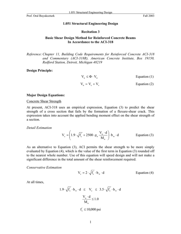
1.051 Structural Engineering Design Prof. Oral Buyukozturk Fall 2003 1.051 Structural Engineering Design Recitation 3 Basic Shear Design Method for Reinforced Concrete Beams In Accordance to the ACI-318 Reference: Chapter 11, Building Code Requirements for Reinforced Concrete ACI-318 and Commentary (ACI-318R), American Concrete Institute, Box 19150, Redford Station, Detroit, Michigan 48219 Design Principle: Vu ≤ Φ ⋅ Vn Equation (1) Vn = Vc + Vs Equation (2) Major Design Equations: Concrete Shear Strength At present, ACI-318 uses an empirical expression, Equation (3) to predict the shear strength of a cross section that fails by the formation of a flexure-shear crack. This expression takes into account the applied bending moment effect on the shear strength of a section. Detail Estimation ⎛ V ⋅d ⎞ Vc = ⎜⎜1.9 ⋅ f c' + 2500 ⋅ ρw u ⎟⎟ ⋅ b w ⋅ d Mu ⎠ ⎝ Equation (3) As an alternative to Equation (3), ACI permits the shear strength to be more simply evaluated by Equation (4), which is the value of the first term in Equation (3) rounded off to the nearest whole number. Use of this equation will speed design and will not make a significant difference in the total amount of the shear reinforcement required. Conservative Estimation Vc = 2 ⋅ f c' ⋅ b w ⋅ d At all times, 1.9 ⋅ f c' ⋅ b w ⋅ d ≤ Vc ≤ 3.5 ⋅ f c' ⋅ b w ⋅ d Vu ⋅ d ≤ 1.0 Mu f c' ≤ 10,000 psi 1 Equation (4) 1.051 Structural Engineering Design Prof. Oral Buyukozturk Fall 2003 Reinforcing Steel Shear Strength Vs = At all times, Av ⋅ f y ⋅ d s Equation (5) f y ≤ 60,000 psi =============================================================== Index Vu Mu Vn Vc Vs Φ = = = = = = = = factored applied shear factored applied moment nominal shear strength of a section shear strength of concrete shear strength of reinforcing steel strength reduction factor 0.85 for shear design ratio of tension reinforcement = As bw ⋅d bw d = = fy f ’c Av s = = = = web width of section, in. distance from extreme compression fiber to centroid of tension reinforcement, in. specified yield strength of reinforcement, psi specified compressive strength of concrete, psi area of shear reinforcement within distance s horizontal distance between bars ρw Equation (6) =============================================================== Basic Design Procedure: 1. 2. 3. From the applied load, determine the shear force diagram (SFD) and bending moment diagram (BMD) using the factored service loads. Establish the shear strength Vc of the concrete. For members subject to shear and moment only (i.e. no axial force), using either Equation (3) or Equation V ⋅d (4). Make sure that u ≤ 1.0 and Vc ≤ 3.5 ⋅ f c' ⋅ b w ⋅ d . Equation (3) will Mu predict a significantly greater value of Vc than Equation (4) only in regions where the moment Mu is small. If an axial force also acts, (come see me and I will tell you) Vc will be different. In addition, the value of the concrete strength is not to exceed 10,000 psi, which is considered high strength. For slabs, footings, shallow beams, and all other members that are generally reinforced for moment only, verify that Vu ≤ Φ ⋅ Vc . If the otherwise, the 2 1.051 Structural Engineering Design Prof. Oral Buyukozturk 4. Fall 2003 shear capacity of the cross section can be raised by increasing the depth of the cross section. Stirrups are not very effective in shallow members because the compression zone lacks the depth required to anchor the force in the stirrups if the steel is stressed to its yield point. For beams that are not shallow, reinforcement is required in regions where Φ ⋅ Vc Vu ≥ . The procedure to establish the stirrup spacing depends on the 2 relative magnitude of Vu and Φ ⋅ Vc . There are altogether three cases: Case 1 Φ ⋅ Vc 2 Vu ≥ but Vu ≤ Φ ⋅ Vc Use minimum reinforcement 50 ⋅ b w ⋅ s fy A v,min = Stirrup spacing is the smallest of s= s= d 2 Av ⋅ f y 50 ⋅ b w s = 24 in Case 2 Vu ≥ Φ ⋅ Vc and Vs ≤ 8 ⋅ f c' ⋅ b w ⋅ d The required shear capacity of the stirrups is Vs = Vu − Vc Φ After Vs has been determined, stirrup spacing can be established by 3 1.051 Structural Engineering Design Prof. Oral Buyukozturk Fall 2003 s= Av ⋅ f y ⋅ d Vs Also, the spacing is subjected to the following restrictions: Shear carried by reinforcement, Vs Maximum spacing, smax Vs ≤ 4 ⋅ f c' ⋅ b w ⋅ d Av ⋅ f y d but not to exceed 24 in or not to exceed 2 50 ⋅ b w Vs ≥ 4 ⋅ f c' ⋅ b w ⋅ d Av ⋅ f y d but not to exceed 12 in or not to exceed 4 50 ⋅ b w Case 3 Vs > 8 ⋅ f c' ⋅ b w ⋅ d This signifies that the cross section is too small. To prevent one of several possible brittle modes of failure associated with high shear stress, the cross-sectional area must be increased. Special Note: ACI Code 11.1.3 permits the stirrups adjacent to a support to be sized for the shear that exists d inches out from the face of the support. This provision recognizes that a crack adjacent to a support whose reaction induces compression into a beam will have a horizontal projection of at least d in; therefore the maximum shear force that must be transmitted across the potential failure plane closest to the support will be equal to the reaction reduced by any external forces applied to the beam within a distance d of the support. If a support does not introduce compression into a member, the critical section for shear should be taken at the face of the support. For this situation the state of stress in the joint should also be studied to determine whether special reinforcement is required. If a concentrated load is applied to a beam between the support and the critical section at d, the design is also based on the magnitude of the shear at the face of the support. 4


