Document 13488507
advertisement
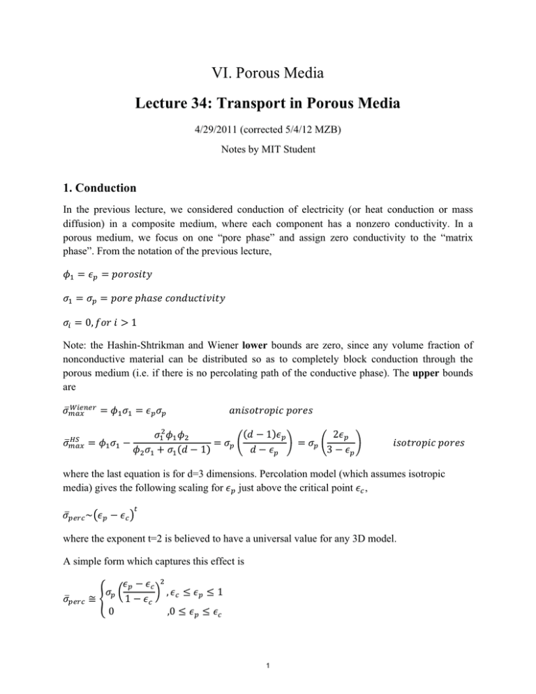
VI. Porous Media Lecture 34: Transport in Porous Media 4/29/2011 (corrected 5/4/12 MZB) Notes by MIT Student 1. Conduction In the previous lecture, we considered conduction of electricity (or heat conduction or mass diffusion) in a composite medium, where each component has a nonzero conductivity. In a porous medium, we focus on one “pore phase” and assign zero conductivity to the “matrix phase”. From the notation of the previous lecture, 1 = Ep = porosity (1 = (p = pore phase conductivity (i = O, for i > 1 Note: the Hashin-Shtrikman and Wiener lower bounds are zero, since any volume fraction of nonconductive material can be distributed so as to completely block conduction through the porous medium (i.e. if there is no percolating path of the conductive phase). The upper bounds are Wiener (max = (max = 1 (1 = Ep (p anisotropic pores (1 1 (1 � (1 1 (1 1 = (p 1 Ep Ep = (p Ep � Ep isotropic pores where the last equation is for d=3 dimensions. Percolation model (which assumes isotropic media) gives the following scaling for Ep just above the critical point Eo , (���o � Ep Eo � where the exponent t=2 is believed to have a universal value for any 3D model. A simple form which captures this effect is (���o � (p O Ep 1 Eo Eo , Eo � Ep � 1 ,O � Ep � Eo 1 since 𝜎!"#$ → 𝜎! as 𝜖! → 1. Note that this lies between the Hashin-Shtrikman bound and the lower bound. In electrochemical engineering, it is common to use the empirical Bruggeman formula !/! 𝜎! = 𝜖! 𝜎! As shown in the figure below, this lies close to the Hashin-Shtrikman upper bound, especially for large 𝜖! . Therefore, the Bruggeman formula could represent an isotropic medium with ample percolating pathways of unblocked pores, similar to the core-shell microstructure (composed of spheres with conducting shells and non-conducting cores) that attains the HS upper bound. This makes sense in porous electrodes, since they are often fabricated from grains and powders soaked in a liquid electrolyte, which effectively coats the particles and percolates through the system. Where this approximation breaks down is at low porosity, where percolation effects can become important with an increasing number of blocked “dead end” pores, and this is reflected in the lower Bruggeman conductivity compared to the HS upper bound (which is attained by microstructures without any blocked pores). 1 Wiener Hashin−Shtrikman Percolation Bruggeman 0.9 0.8 σeff/σp 0.7 0.6 0.5 0.4 0.3 0.2 0.1 0 0 0.1 0.2 0.3 0.4 0.5 0.6 εp 0.7 0.8 0.9 1 [Figure credit: Todd Ferguson] Conductivity bounds and models in d=3 dimensions. 2 2. Diffusion The effective conductivity determines the macroscopic current density 𝐽 = −𝜎𝛁𝜙. In the case of diffusion, the net flux is 𝐹 = −𝜎! 𝛁𝑐, where c is the concentration in the pores (which is constant in equilibrium, even if the porosity varies in space). Macroscopic conservation of mass requires 𝜕𝑐 +𝛁∙𝐹 =0 𝜕𝑡 Where 𝑐 = 𝜖! 𝑐 is the volume-averaged concentration. 𝜕𝑐 = 𝜎! 𝛁 ! 𝑐 = 𝐷𝛁 ! 𝑐 𝜕𝑡 𝑜𝑟 𝜕𝑐 = 𝐷𝛁 ! 𝑐 𝜕𝑡 Where 𝐷 = !! !! is the effective diffusivity in the porous medium. Note: the Wiener upper bound implies 𝐷 ≤ 𝐷! , since 𝜎 ≤ 𝜖! 𝜎. Therefore, we can interpret the reduction of D in the pores via an effective extension of the path length for diffusion by a factor called tortuosity 𝜏! . 𝐿! = 𝜏 ! 𝐿 𝛁 = 𝜏! 𝛁! → 𝐷= 𝜕𝑐 = 𝐷! 𝛁!! 𝑐 𝜕𝑡 𝐷! 𝜏!! So we can recover the same diffusion equation as in the free solution only with a stretched spatial coordinate system. Thus, we arrive at the following interpretation of the diffusive mean conductivity. 𝜎! = 𝐷! 𝜖! 𝜏!! Note: if 𝜎! is a tensor, then tortuosity is also a tensor given by 𝜏! = 𝐷! 𝜖! 𝜎!!! !/! . For the models and bounds above, we have the following tortuosity (noting that 𝜏! = 1 when 𝜖! = 1): 3 TpWiener = 1 (lower bound, attained by aligned stripes); d − εp 3− εp = (lower bound for isotropic pores); d −1 2 τ pHS = �1�4 T� = Ep (Bruggeman empirical formula); Ep T���o � � 1 � l� � l� lp , Eo � Ep �1 ,O � Ep � Eo Note: tortuosity makes no sense when conductivity becomes significantly reduced by loss of percolation, since it is not the longer path length but rather the many “dead ends” and few percolating paths that lower the conductivity. The figure below shows the tortuosity according to the above models 4 Wiener Hashin−Shtrikman Percolation Bruggeman Tp 3.5 3 τp 2.5 2 1.5 1 0.5 Eo 0 0 0.1 0.2 εc 0.3 Ep 0.4 0.5 εp 0.6 0.7 0.8 0.9 1 Figure: Tortuosity vs. porosity for bounds and models in d=3 dimensions [T. Ferguson] 4 3. Ion transport (neglect convection and electroosmotic flow) Surface charge qs on the pore wall Microscopic Nernst-Planck equation in the pores (NOT Laplace’s equation as before): 𝜕𝑐! + 𝛁 ∙ 𝐹! = 0 𝜕𝑡 𝐹! = −𝐷! 𝑐! 𝛁𝜇! 𝜇! = 𝜇! /𝑘! 𝑇 𝜇! = 𝑘! 𝑇 ln 𝛾! 𝑐! + 𝑧! 𝑒𝜙 Poisson’s equation gives: −𝜀! ∇! 𝜙 = 𝜌 = ! 𝑧! 𝑒𝑐! Boundary condition (no reaction, fixed surface charge): −𝜀! 𝑛 ∙ ∇𝜙 = 𝑞! 𝑛 ∙ 𝐹! = 0 Macroscopic PNP equation: 𝜕𝑐! + 𝛁 ∙ 𝐹! = 0 𝜕𝑡 𝐹! = −𝐷! 𝑐! 𝛁𝜇! 𝜇! ≅ 𝑐𝑜𝑛𝑠𝑡𝑎𝑛𝑡, 𝑎𝑐𝑟𝑜𝑠𝑠 𝑝𝑜𝑟𝑒𝑠 𝑎𝑛𝑑 𝑠𝑚𝑎𝑙𝑙 𝑙𝑒𝑛𝑔𝑡ℎ 𝑠𝑐𝑎𝑙𝑒𝑠, 𝑒𝑣𝑒𝑛 𝑡ℎ𝑜𝑢𝑔ℎ 𝑐 𝑎𝑛𝑑 𝜙 𝑣𝑎𝑟𝑦 𝑞𝑢𝑖𝑐𝑘𝑙𝑦. 5 𝐷𝑒𝑓𝑖𝑛𝑒 𝜌 = 𝑧! 𝑒𝑐! ! −𝛁 ∙ 𝜀∇𝜙 = 𝜌 + 𝜌! Where 𝜌! = 𝑎! 𝑞! , 𝑎! = !"#$ !"#$%&' !"#! !"#$%& . In the limit of the double layer, 𝑐! ≅ 𝑐𝑜𝑛𝑠𝑡𝑎𝑛𝑡 𝑖𝑛 𝑡ℎ𝑒 𝑝𝑜𝑟𝑒 𝑏𝑢𝑙𝑘 𝑠𝑜𝑙𝑢𝑡𝑖𝑜𝑛 = 𝑐! /𝜖! , and 𝜙 ≅ 𝜙 = 𝑐𝑜𝑛𝑠𝑡𝑎𝑛𝑡 𝑜𝑢𝑡𝑠𝑖𝑑𝑒 𝑑𝑜𝑢𝑏𝑙𝑒 𝑙𝑎𝑦𝑒𝑟 and 𝜀 → 0: 𝜌 + 𝜌! = 0 𝑇ℎ𝑖𝑛 𝑑𝑜𝑢𝑏𝑙𝑒 𝑙𝑎𝑦𝑒𝑟 𝜌! = 𝑠𝑢𝑟𝑓𝑎𝑐𝑒 𝑐ℎ𝑎𝑟𝑔𝑒 𝑣𝑜𝑙𝑢𝑚𝑒 This is just macroscopic neutrality condition. 6 MIT OpenCourseWare http://ocw.mit.edu 10.626 Electrochemical Energy Systems Spring 2014 For information about citing these materials or our Terms of Use, visit: http://ocw.mit.edu/terms.
