Document 13475347
advertisement

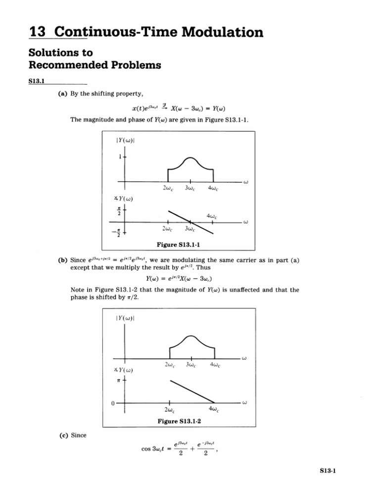
13 Continuous-Time Modulation Solutions to Recommended Problems S13.1 (a) By the shifting property, x(t)ejawc t X(w - - 3we) = Y(w) The magnitude and phase of Y(w) are given in Figure S13.1-1. IY(W)I 2w.. 3wc 4wc 4Y(W) 2 4w. 2w~ 3w~ Figure S13.1-1 (b) Since ej 3 wc+ji2 e r/2 e 3 wt, we are modulating the same carrier as in part (a) except that we multiply the result by eij/ 2 . Thus Y(w) = ej' 2X(w - 3c) Note in Figure S13.1-2 that the magnitude of Y(w) is unaffected and that the phase is shifted by ir/2. |Y(w)| w() I 4 Y(w) 7r -­ 2wC 4wc Figure S13.1-2 (c) Since ej3wct cos 3 xeot = 2 2 g + -j3wct 2' S13-1 Signals and Systems S13-2 we can think of modulation by cos 3wet as the sum of modulation by , Sj3eet 2 t -j3wc and 2 Thus, the magnitude and phase of Y(o) are as shown in Figure S13.1-3. Note the scaling in the magnitude. jY(w)I 1 3ic -3wc 4 Y(w) 3w -3w 2 c Figure S13.1-3 (d) We can think of modulation by sin 3wet as the sum of modulation by e -j3wct ej3wct -jr/2 and 2 -fr/2 2 Thus, the magnitude and phase of Y(w) are as given in Figure S13.1-4. Note the scaling by 1in the magnitude. IY(w)I 3oc -3oic 4 Y(W) -4c 2c -2wc 4 Figure S13.1-4 (e) Since the phase terms are different in parts (c) and (d), we cannot just add spec­ tra. We need to convert cos 3wct + sin 3wet into the form A cos(3wet + 0). Note Continuous-Time Modulation / Solutions S13-3 that cos(a - #) Let a = 3wet and # = 7r/ 4 cos a cos # + sin a sin # = . Then - cos (3xet (cos 3cet + sin 3wet) = Thus -r cos 3Uet + sin 3wet = \/2 cos (3wet Now we write c(t) as 2e 2 3 wct - + ("!) 2 e 2 j3wt -(r/4)J Modulating by each exponential separately and then adding yields the magni­ tude and phase given in Figure S13.1-5. (Note the scaling in the magnitude.) Y(W)| 2 3co~ 3 Ct -3co~ -3wc 4 Y(W) 2wc Figure S13.1-5 S13.2 In Figure S13.2-1 we redraw the system with some auxiliary signals labeled. r, t) r2(t) X x(t) s(t) ir3(t) r4(t) X 1 d(t) m(t) Figure S13.2-1 y(t) Signals and Systems S13-4 By the modulation property, Ri(w), the Fourier transform of ri(t), is 1 [X(w) * S(w)] 27r R1(w) = - Since S(w) is composed of impulses, Ri(w) is a repetition of X(w) centered at -2c, 0, and 2 we, and scaled by 1/(27r). See Figure S13.2-2. R 1 (w) 1 2ir Figure S13.2-2 (a) Since m(t) = d(t) = 1, y(t) is ri(t) filtered twice by the same ideal lowpass filter with cutoff at we. Thus, comparing the resulting Fourier transform of y(t), shown in Figure S13.2-3, we see that y(t) = 1/(27r)x(t), which is nonzero. Y(W) 1 2ir WCo Figure S13.2-3 (b) Modulating ri(t) by ei-c' yields R 1 (w - we) as shown in Figure S13.2-4. R 1 (o - wc) 1 27 S. Figure S13.2-4 Continuous-Time Modulation / Solutions S13-5 Similarly, modulating by e ~j'Wyields Ri(o + coc) as shown in Figure S13.2-5. R I(w + wc) 1 2n -2wc -c Figure S13.2-5 Since cos wot = (ewct + e -iwct)/ 2 , modulating ri(t) by cos wct yields a Fourier transform of r 2(t) given by Ri(w - wc) + Ri(w + wo) 2 Thus, R 2 (W) is as given in Figure S13.2-6. R 2(CJ) 2-t -2Fc II -wc -- oc Wc Figure S13.2-6 After filtering, R3(o) is given as in Figure S13.2-7. R 3(W) 1 -- c Wc Figure S13.2-7 2 co 23c. Signals and Systems S13-6 R 4 (w) is given by shifting R 3 (W) up and down by we and dividing by 2. See Figure S13.2-8. R 4 (W) 1 4w -2c -wc Wc 2.c Figure S13.2-8 After filtering, Y(w) is as shown in Figure S13.2-9. Y(W) 1 4w Figure S13.2-9 Comparing Y(w) and X(w) yields y(t) 1 -- x(t) = 4-r (c) Since g sin wet jwct = _ -jwct 2j then R 2 (w) = Ri(w - oc) - Ri(w + we) 2j which is drawn in Figure S13.2-10. R2(W) I/ -4I 4w1 Figure S13.2-10 After filtering, R 3(x) = 0. Therefore, y(t) = 0. Continuous-Time Modulation / Solutions S13-7 (d) In this case, it is not necessary to know r 3 (t) exactly. Suppose r 3 (t) is nonzero, with RA(W) given as in Figure S13.2-11. After modulating by d(t) = cos 2cot, R 4 (W) is given as in Figure S13.2-12. R 4 (w) -~oc -2wc c 2o Figure S13.2-12 After filtering, y(t) = 0 since R 4(w) has no energy from -we, (e) For this part, let us calculate R 2(w) explicitly. RI(w - 2wc) + R,(w + 2wc) R2(W) = n which is drawn in Figure S13.2-13. R 2 (W) 1 4ff -2wc Wc Wc Figure S13.2-13 2wc to we,. Signals and Systems S13-8 After filtering, R 3 (w) is as shown in Figure S13.2-14. R 3 (w) 47r -coc Wc Figure S13.2-14 Modulating again yields R 4(w) as shown in Figure S13.2-15. R 4 (W) 1 c S c Figure S13.2-15 Finally, filtering R 4 (w) gives the Fourier transform of y(t), shown in Figure S13.2-16. Y(o) 8ir Figure S13.2-16 Thus, y(t) = 1- x(t) 87r S13.3 (a) The demodulator signal w(t) is related to x(t) via W(t) = (cos wdt) (cos Wt)x(t) Continuous-Time Modulation / Solutions S13-9 Since cos A cos B = 1[cos(A - B) + cos(A + B)], w(t) i[cos(Aw)t + cos(Aw + = - 2we)t]x(t) + -[cos(Aw + 2wc)t]x(t) i[cos(A)t]x(t) The first term is bandlimited to ± (wM + IAwl), while the second term is bandlimited from Aw + 2wc - wM to Aw + 2wc + wM. Thus after filtering, only the first term remains. Therefore, the output of the demodulator lowpass filter is given by .x(t)cos AWt. (b) Consider first IAw I > wM Then for X(w) as given, ix(t)cos Awt has a Fourier transform as shown in Figure S13.3-1. _| I Iol -lAwi Figure S13.3-1 For IAwl <wM, there is some overlap. See Figure S13.3-2. O<IAWK 1.TM 1 M O <IAWl<wJ M M 1 14 -JAWI lwl -awI AW Figure S13.3-2 S13.4 (a) In this case, y(t) = [A + cos wL)Mt cos(Wct + Oc) But ~ Oc)+ cOs((WM + Oc)t + Cos oMt cos(Wct + O') = 1[cos((WM ~ cjt cj] Thus, 1 2 = 2 + eiwct + e -Jwct 2 1 ejoce -i(WM-Wc)t 4 + + -e ijceJ(WM- C)t 4 1 ejOCe(WM+)dt 4 1 2 O + 1cos((WM + W')t + Oc w)t y(t) = A cos(wct + Oc) + 1cos((wM + ! e 4 -joce -j(wm±(cc) t Signals and Systems S13-10 We recognize that the preceding expression is a Fourier series expansion. Using Parseval's theorem for the Fourier series, we have TO k= Thus, P,=2(A) + A2 2 42 Since max Ix(t)| 1 A A then 1 9 2M 1 4, 2 as shown in Figure S13.4-1. Py 3 1 4M 1 1 overmodulation Figure S13.4-1 (b) The power in the sidebands is found from P, when A = 0. Thus, P,y = efficiency is = E= 2 1/(2M ) + } which is sketched in Figure S13.4-2. 2 + M2 > and the Continuous-Time Modulation / Solutions S13-11 Solutions to Optional Problems S13.5 (a) Using the identity for cos(A + B), we have A(t)cos(oct + Oc) = A(t) (cos 0e cos oct - sin 0c sin oct) Thus, we see that x(t) = A(t) cos 0c, y(t) = -A(t) sin 0, Therefore, z(t) = A(t)cos(oct + 0c) = x(t)cos wct + y(t)sin wot (b) Consider modulating z(t) by cos oc. Then z(t)cos wot = x(t)cos2 wet + y(t)sin oct cos wct Using trigonometric identities, we have z(t)cos oct = 2 + 2 cos 2et + 2 sin 2 wet If we use an ideal lowpass filter with cutoff wc and if A(t), and thus x(t), is bandlimited to _oc, then we recover the term x(t)/2. Thus the processing is as shown in Figure S13.5-1. z (t) x (t) X2: -WC C Cos coCt Figure S13.5-1 (c) Similarly, consider z(t)sin oct = x(t)cos oct sin wct + y(t)sinswct = 2 sin 2wet + y) 2 2 y) cos 2wct 2 Filtering z(t) sin wct with the same filter as in part (b) yields y(t), as shown in Figure S13.5-2. Signals and Systems S13-12 z(t) eyt rX sin coc t Figure S13.5-2 (d) We can readily see that x 2(t) + y 2(t) = A 2 (t) (cos 20e + sin20') = A 2(t) Therefore, A(t) = x 2 (t) + y 2(t). The block diagram in Figure S13.5-3 sum­ marizes how to recover A(t) from z(t). z(t) A (t) sin ct Figure S13.5-3 Note that to be able to recover A(t) in this way, the Fourier transform of A(t) must be zero for o > oc| I and A(t) > 0. Also note that we are implicitly assum­ ing that A(t) is a real signal. S13.6 From Figures P13.6-1 to P13.6-3, we can relate the Fourier transforms of all the signals concerned. SI(M) = S2(W) = - 2j [X (W x [ X ' 010-2) -O X( + X o ­ Thus, Si(w) and S2(O) appear as in Figure S13.6-1. Continuous-Time Modulation / Solutions S13-13 SI (w) S2(w) 1 2 0 0 2 2 Figure S13.6-1 After filtering, S 3(w) and S 4(w) are given as in Figure S13.6-2. S3 (w) S4 (Co) Figure S13.6-2 S5(U)is as follows (see Figure S13.6-3): [ S5(W)= 1 S3 ( W- We -) - S3 (W + W, +2 Note that the amplitude is reversed since (1/2j)(1/2j) = -I. Signals and Systems S13-14 Ss (C) 1 4 -- oc c 4 Figure S13.6-3 S6 (w) is as follows and as shown in Figure S13.6-4. S6(w)= Finally, Y(w) = S4 -cw- + S4 2 + We + 2)] x S5(w) + S6 (w), as shown in Figure S13.6-5. Y(W) 2 -­ I______ oc ~-oc CO Figure S13.6-5 Thus, y(t) is a single-sideband modulation of x(t). S13.7 Note that qI(t) = [si(t)cos wot + s 2 (t)sin wot]cos wot = s 1 (t)cos 2xot + s 2(t)sin wot cos wot Using trigonometric identities, we have qi(t) = isi(t) + isi(t)cos 2wet + is (t)sin 2 2wot Thus, if s 1(t) is bandlimited to ± wo and we use the filter H(w) as given in Figure S13.7, y 1(t) will then equal s 1(t). Continuous-Time Modulation / Solutions S13-15 H(w) 2 Figure S13.7 Similarly, q 2(t) = si(t)cos wet sin wot + s 2(t)sin 2Wot SIM sin 2w t + s 2 (t) s 2 (t) 2wot 2 2 2 Using the same filter and imposing the same restrictions on s 2 (t), we obtain y 2(t) = s2 (t). S13.8 (a) X(w) is given as in Figure S13.8-1. X(w) -1 WM -ojM Figure S13.8-1 For Y(w), the spectrum of the scrambled signal is as shown in Figure S13.8-2. Y(W) Figure S13.8-2 Thus, X(w) is reversed for w > 0 and w < 0. Signals and Systems S13-16 (b) Suppose we multiply x(t) by cos Denoting z(t) = x(t)cos Wot. wmt, we find that Z(w) is composed of scaled versions of X(w) centered at ± wM. See Figure S13.8-3. Z(W) -2wm M 2 WM WM Figure S13.8-3 Filtering z(t) with an ideal lowpass filter with a gain of 2 yields y(t), as shown in Figure S13.8-4. x (t) MX 2. _M iy(t) IjMJ Cos WMt Figure S13.8-4 (c) Suppose we use the same system to recover x(t). Let y(t)cos R(w) is as given in Figure S13.8-5. Wmt = R(o) 1 2 -2wM WM WM -- "M ljM Figure S13.8-5 Filtering with the same lowpass filter yields x(t). 2wM r(t). Then MIT OpenCourseWare http://ocw.mit.edu Resource: Signals and Systems Professor Alan V. Oppenheim The following may not correspond to a particular course on MIT OpenCourseWare, but has been provided by the author as an individual learning resource. For information about citing these materials or our Terms of Use, visit: http://ocw.mit.edu/terms.


