MAGNETIC FORCES ON FLAT SURFACES ∫ v w
advertisement
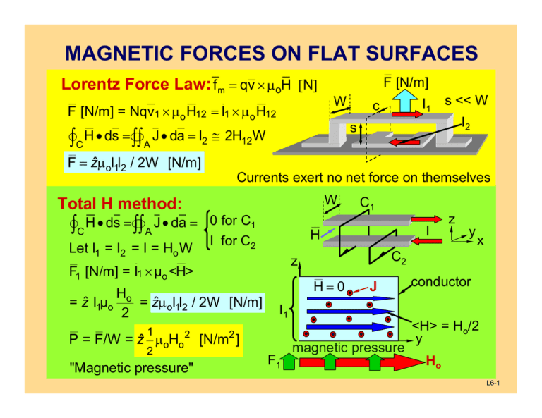
N MAGNETIC FORCES ON FLAT SURFACES Lorentz Force Law: f m = qv × μoH [ ] F [N/m] W F [N/m] = Nqv1 × μo H12 = I1 × μ o H12 W Let I1 = I2 = I = Ho W 0 for C1 P = F/W = ẑ μ oHo 2 2 "Magnetic pressure" I H=0 J I1 2 [N/m ] F1 z y x C2 z Ho = zˆμoI1I2 / 2W [N/m] 2 1 C1 H I for C2 F1 [N/m] = I1 × μo <H> = zˆ I1μo I2 Currents exert no net force on themselves Total H method: ∫∫ A J • da = v∫C H • ds = w s << W s ∫∫ A J • da = I2 ≅ 2H12 W v∫ C H • ds = w F = ẑμ oI1I2 / 2W [N/m] I1 c magnetic pressure conductor <H> = Ho/2 y Ho L6-1 ROTARY WIRE MOTOR Single wire loop spinning in uniform H: F [Nm-1] = I × μo H T = v∫ r × F ds = r2WIμoH ẑ [Nm] c f N T = IAμoH ẑ (A is loop area, N = 1 turn) ds T = NIAμoH ẑ for N-turn coil Axial forces from wires at ends cancel Torque = f(θ): T[Nm] 0 With commutator π 2π T, ẑ C S H r W θ I NIμoH(θ)A θ Commutators: Switch currents to maximize torque Can have N coils and 2N brushes θ spring-loaded carbon brushes L6-2 MOTOR BACK VOLTAGE Force f e on electron inside moving wire: f e = − e ( Ee + v × μo H ) = 0 Open-circuit wire: −eEe ⇒ Ee = − v × μo H inside H −ev × μo H v Open-circuit voltage: Φ = Ee W = vμoHW [V] Force balance Mechanical power output, N turns: Pm = ωT = ωNIAμoH [W] I = (V - Φ)/R Φ = 2NvμoHW = 2NωrμoHW = NAμoHω Pm = ωN(V - NAμoHω)AμoH/R = ωK1 – ω2K2 ωmax = V/NAμoH Φp = V/2 Φ+ H - Pm(ω) = 2ωp W v,f,x̂ R Pp 0 -e motor ωp ωmax ω + - V I + Φ - generator L6-3 RELUCTANCE MOTOR FIELDS 2-Pole Reluctance Motor: ∇ • B = 0 ⇒ Bμ ≅ Bgap ⇒ Hμ ≅ μo μ Hgap << Hgap [ > ~104 ] μ μo ∫A J • da = NI = v∫c H • ds = v∫c (Hgap + Hμ ) • ds ≅ 2bHgap (if Hμ v∫c ds << 2bHgap ) gap b Therefore Hgap ≅ NI [A / m] 2b T μ μ μ μ rotor ds Area A θ rotor stator stator D N turns I +V- I + V - D N turns L6-4 RELUCTANCE MOTOR TORQUE Fields: Hgap = NI 2b T μ Magnetic Flux Linkage Λ: gap b μ rotor Λ = N∫∫ B•da = NμoHgap A gap A = N2μoIA gap /2b (A gap = RDθ) Λ = LI ⇒ L = N2μoRDθ/2b 1 2 1 Λ2 w m = LI = 2 2 L θ stator I +V- D N turns Set V = dΛ/dt = 0: dw m Λ 2 dL-1 Λ2 2b 2 T == = I [ ∝ ], Λ=NμoHgapRθD 2 2 dθ 2 dθ 2 N μoRDθ dV 1 = μoHgap2 2bD R = Wgap olume [Nm] Torque 2 dθ We power coil until overlap is maximum, then coast until it is zero Magnetic pressure = Energy density [J/m3 = N/m2] L6-5 ¾-POLE RELUCTANCE MOTOR Winding Excitation Plan: First excite windings A and B, A pulling pole 1 into pole B. Pole area A = constant, temporarily. When Δθ = π/3, excite B and C. When Δθ = 2π/3, excite C and A. Repeating this cycle results in C nearly constant clockwise torque. A 1 μ 4 θ B 2 B μ C To go counter-clockwise, excite BC, then AB, then CA. Torque: Only one pole is being pulled in here; the other excited winding has either one rotor pole fully in, or one entering and one leaving that cancel. Many pole combinations are used (more poles, more torque). L6-6 ELECTRIC AND MAGNETIC PRESSURE Electric and magnetic pressures equal the field energy densities, J/m3 Both field types only pull along their length, and only push laterally The net pressure is the difference between two sides of any boundary 1 2 Magnetic pressure Pm = μo | H | [N/m2] or [J/m2] 2 Area μ = ∞A μ=∞ Force fm = APm Force fm = BPm Force fm = APm σ=∞ Area A Area B 1 2 Electric pressure Pe = εo | E | [N/m2] or [J/m2] 2 Area σ=∞ A σ=∞ Force fe = APe Force fe = BPe Area B L6-7 FORCES ON NEUTRAL MATTER Kelvin polarization force density: If ∇ × E = 0 = ∇ • E, then: Field gradiants ⊥ E ⇒ E is curved Curved E pulls electric dipoles + ++ + +++ ε > εo -E - - into stronger field regions for ε>εo If ∇ × H = 0 = ∇ • B, then: Field gradiants ⊥ H ⇒ H is curved stronger field regions for μ > μo - fx/2 x fx/2 + - z μ > μo B + d y• Kelvin magnetization force density: Curved H pulls current loops into + V - I μo μ > μo Induced current loop B1 > B2 B2 f × x2 B1 • fx1 L6-8 MIT OpenCourseWare http://ocw.mit.edu 6.013 Electromagnetics and Applications Spring 2009 For information about citing these materials or our Terms of Use, visit: http://ocw.mit.edu/terms.


