The Shape of a Rain Drop as determined from the... John Caleb Speirs Classical Mechanics PHGN 505
advertisement
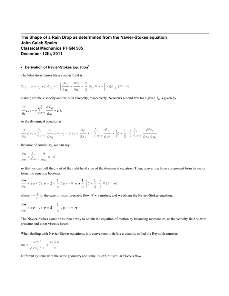
The Shape of a Rain Drop as determined from the Navier-Stokes equation John Caleb Speirs Classical Mechanics PHGN 505 December 12th, 2011 Derivation of Navier-Stokes Equation1 The total stress tensor for a viscous fluid is ¶ vi Tij = Ρ vi vj + p ∆ij - Η + ¶ xj ¶ vj 2 - ¶ xi 3 ∆ij Ñ × v - Ζ∆ij HÑ × vL Η and Ζ are the viscocity and the bulk viscocity, respectively. Newton's second law for a given Tij is given by ¶ ¶t Ρv k = -â 3 ¶ Tkl l=1 ¶ xl + Ρ fk so the dynamical equation is ¶ ¶t Ρ vi + â 3 ¶ j=1 ¶ xj Ρ vi vj = Ρ fi - ¶Ρ ¶ xi +Ηâ 3 j=1 ¶2 vi 1 + Ζ+ ¶ x2 3 Η â 3 j=1 ¶2 vj ¶ xi ¶ xj Because of continuity, we can say ¶Ρ ¶t +â 3 ¶ j=1 = 0 ¶ xj so that we can pull the Ρ out of the right hand side of the dynamical equation. Then, converting from component form to vector form, the equation becomes ¶v ¶t + Hv × ÑL v = f - 1 Ρ Ñ p + v Ñ2 v + 1 1 Ζ+ Ρ 3 Η Ñ HÑ × vL where v = Ρ . In the case of incompressible flow, Ñ·v vanishes, and we obtain the Navier-Stokes equation: Η ¶v ¶t + Hv × ÑL v = f - 1 Ρ Ñ p + v Ñ2 v The Navier-Stokes equation is then a way to obtain the equation of motion by balancing momentum, or the velocity field v, with pressure and other viscous forces. When dealing with Navier-Stokes equations, it is convenient to define a quantity called the Reynolds number: Re = Ρ v0 2 Ρ v v0 l = v0 l Ρ Η Different systems with the same geometry and same Re exhibit similar viscous flow. Summary of previous work 2 FinalProject1.nb Summary of previous work Feng and Beard2 combined the Navier-Stokes equation with computational modelling to theoretically determine the shape of a raindrop. Their work builds off of previous experimental3 and analytical4 attempts at verifying a mathematical description of the shape of a falling raindrop. Experimental efforts focused mainly on high-speed photography3 , which revealed that water drops of diameter >2 mm would tend to take a hamburger shape (spherical on top, flat on bottom) while falling at terminal velocity and drops < 1mm would take on a spherical shape. However, results were inconsistent until, in early 1970, Pruppacher and Beard3 and Pruppacher and Pitter3 developed a vertical wind tunnel that allowed them to freely suspend drops in the upward airstream and take high quality photographs. Raindrop shape is essentially transient in nature, with the form oscillating around an equilibrium shape3 . This equilibrium shape can be determined by considering the traction boundary condition which includes interfacial stresses from fluid flows internal and external to the drop, and also hydrostatic pressure due to gravity2 . Thus, the equilibrium shape can be determined through numerical modelling of the Navier-Stokes equation to obtain the transient form of the drop and then to time-smooth the solutions by taking a large number of solutions at different time steps and averaging them together. Mathematical models range from the Navier-Stokes method to solving the linear Young-Laplace equation describing the local balance between surface curvatures with surface tension and pressure difference distribution across the interface: 1 Σ 1 + R1 = Dp R2 with Dp being the pressure difference 4 . This model also requires numerical solutions, though is more analytically driven to begin with. This model was approximate as it didn't include viscous forces. Nevertheless, it was surprisingly accurate for smaller drop sizes. Since these models focus on the external aerodynamic pressure and internal hydrostatic pressure, it is suggested that viscous stresses and internal circulation stresses are negligible when compared to the dynamic pressure. Governing Equations The three-dimensional Navier-Stokes equation can be simplified by assuming a symmetric shape about the z-axis. Taking a drop of volume 4 3 Π R3 , constant density Ρ, viscosity Μ, and surface tension Γ, falling with constant gravity g, the Navier-Stokes equation becomes Ρ 2 Re v × Ñ v = Ñ × T T = - p + ΜAÑ v + HÑ vLT E with inside the drop and Ρ 2 Re v × Ñ v = Ñ × Tg Tg = - p + Ñ v + HÑ vLT with outside the drop, where the subscript g is representing gas, or the air through which the drop is falling. Re denotes the Reynolds number, given in this situation as 2 Ρg U R Μg with U the terminal velocity of the drop. The traction boundary condition (which is related closely to the Young-Laplace equation) for the free surface S f is (using cylindrical coordinates and the assumes symmetry about the z-axis) FinalProject1.nb outside the drop, where the subscript g is representing gas, or the air through which the drop is falling. Re denotes the Reynolds number, given in this situation as 2 Ρg U R Μg with U the terminal velocity of the drop. The traction boundary condition (which is related closely to the Young-Laplace equation) for the free surface S f is (using cylindrical coordinates and the assumes symmetry about the z-axis) n × ITg - TM = Ca = Μg U Γ 1 dt n dz + Ca ds - pa n + St z n r ds on Sf Hcapillary numberL The unit vector n points from the gas to the liquid. t is the tangent vector and points in the direction of increasing s. Thus, nt = eΘ . pa , the constant excess pressure inside the drop, is an unkown but can be determined by adding a constraint that the volume contained by S f is constant: 2 à r Sf dz 4 ds = ds . 3 St, the Stokes number, HΡ - 1L 2 à zr Sf Ρ g g R2 Μg U , can also be determined by constraining the center-of-mass to remain at the origin: dz ds = 0. ds The Stokes number represents the ratio of buoyancy force and viscous force. Note that the hydrostatic pressure effect due to buoyancy force only appears in the traction boundary condition through St. Other constraints to be made include n·v=0 on S f and r = 0 for the velocity field due to the kinematic condition on S f and the symmetry condition at r = 0. The stress free symmetric condition at the axis of symmetry can be represented ez ·T·er = 0 at r = 0. The work done in 2 used a cylindrical container wall with radius 10 R for the far field boundaries. Several boundary conditions and constraints can be constructed from this container; On Sinlet, which is the surface through which air flow comes (located at z = - 10 in the present modelling), and at the cylinder wall, r = 10 R, the condition for uniform flow velocity is v = ez . At Soutlet (located here as z = 15) the flow condition for hydrodynamic stress is ez × Tg × er = ¶vz ¶r and ez × Tg × ez = 0. (This surface was placed at z = 15 instead of z = 10 to accomodate for the wake caused by the drop). The independent variables of this system are Re, Ca, liquid density Ρ and liquid viscosity Μ, and these need to be specified. The Stokes number, St, can then be specified, and the other relevant quantities can be determined from these variables. 3 4 FinalProject1.nb Methods2, 5, 6 The solution is obtained by discretizing the partial differential equation system with the Galerkin method of weighted residuals using finite-element basis functions.Then, the set of nonlinear algebraic equations is solved by Newton's method of iterations. The weighted residual method takes a differential equation and rewrites it in terms of a set of basis functions. For instance, take a differential operator L operating on some function y(x) in forced differential equation such as L y(x) + f (x) = 0. With a set of basis functions | v >, we can take a test function u = Ú ci | vi > and substitute for y(x).The residual is defined as r(x) = L u(x) + f (x). The main task of a weighted residual method is to find a weight function w(x) such that Ùa w(x) (L u(x) + f (x)) b dx = 0. Galerkin' s method is a special case of this, where the weight functions are the basis functions used to approximate u. We have Ùa b vi(x) (L u(x) + f (x)) dx = 0 and the main task is to find the coefficients, ci, that make this equation true.This results in N nonlinear algebraic equations.Newton' s method of iterations can then be used to linearize these nonlinear equations and solve for the numerical roots to the equations, or in essence, to solve the equation L y(x) + f (x) = 0. Newton' s method is summarized by the equation xn+1 = xn - f Hxn L f ' Hxn L .This equation comes from expanding the equation f(x) = 0 in a taylor series expansion around a suspected root x0 and solving for the root of that function.This results in f Hx0 ) + f ' Hx0 ) (x - x0 ) = 0. Solving for x gets us x1 = x = x0 - f Hx0 L f ' Hx0 L Then we take the value for x and take a taylor series expansion around that value and again solve for x, yielding x2 = x = x1 - f Hx1 L f ' Hx1 L Doing this n times yields the equation above.Here, our f (x) is the weighted nonlinear function obtained by Galerkin' s method, which was evaluated from an integral over the boundary specified by the cylindrical boundary walls.This method can easily be extended to three dimensions. Results Feng and Beard2 used a value Ρ Ρg =800, and initially, Μ Μg =75. Dimensionalizing the equation like this allows the computation to be unitless and thus more robust. They ran the numerical model for drops of various diameters and found regimes of similarity as follows: 800 Μm, 1 mm - 1.5 mm, ³ 2 mm. d = 800 Μm FinalProject1.nb d = 800 Μm For drops of d = 800 Μm, experiment has shown the drops to have steady internal flow patterns, and thus a spherical shape with no oscillation. This is therefore the control for the model to determine if it is accurate. Because of the way the computational problem is set up, we cannot explicity define in the process the drop diameter, but rather have to specify it through the Reynolds number and the Ca. A drop of diameter 800 Μm should have a terminal velocity U = 3.225 m/s with Re = 179.164. Using that as a starting point for the first iteration of the methods yielded a radius of 803.2 Μm. Slight adjustment of the U, the Reynolds number became Re = 177.133 and U = 3.1884 m/s. This yields a d = 800.1 Μm. The shape computed is shown in Appendix A Figure 1. As a quantitative measure of the oblateness of the drop, we can determine the axis ratio Α= zmax - zmin 2 rmax The computed Α for this system was 0.9940, or essentially spherical, as expected. 1 mm < d < 1.5 mm Drops of this size have been observed to oscillate with periodic vortex shedding in the wake of the drop. These interrupt steady internal flow, and therefore interrupt the flow that causes the shape to be spherical. This change can be modelled in changing the value of Μ Μg from 75 to 200. Ρ Ρg remains the same. By following the same course of altering U, we obtain Re=273.229 and U=3.9344 m/s for d=1.0000 mm. This yields an Α of 0.9821. As a test, Μ Μg is varied back to 100, which led to results that were less consistent with previous work, and therefore our value of 200 is a better choice without more accurate knowledge. For a drop of d=1.5 mm and Re=614.906, U=5.9031 m/s, we obtain Α = 0.9576. Note that the axis ration is falling increasingly away from 1 as drop size increases. d ³ 2 mm It should be noted that for drop diameters above 5 mm, the model was found to be increasingly in conflict with previous models, and so the model probably breaks down in that regime. Nevertheless, the results of various drop diameters above 5 mm is shown in Table 1. Table 1: Values of drop diameter, terminal velocity U, Reynolds Number Re, and axis ratio Α d HmmL U HmsL 2 6.4006 3 7.8846 4 8.6012 5 8.839 6 8.8672 7 8.8655 8 8.9412 Out[4]//MatrixForm= Re 504.478 569.18 522.112 436.632 362.304 312.418 291.472 Α 0.9283 0.8528 0.7688 0.6837 0.6029 0.5262 0.4513 An interesting side note to the work presented was that from it, a formula for axis ratio as a function of diameter was delivered: 5 6 FinalProject1.nb Α= 1 - 0.0159 d2.2 d < 2 mm 1.0942 - 0.0864 d + 0.0019 d2 d ³ 2 mm Again noting, however, that the model disagrees with most previous work for d > 5 mm. References 1. A. L. Fetter and J. D. Walecka, Theoretical Mechanics of Particles and Continua (Dover, Mineola, New York, 1980), pp. 438 440. 2. J.Q. Feng and K.V. Beard, Journal of Atmospheric Research, 101, (2011) 480-491 3. Experimental: Lenard, P., 1904. Uber regen. Meteor. Z. 21, 248–262 (for English translation see: 1905 Quart. J. Roy. Meteor. Soc., 31, 62–73.). Magono, C., 1954. On the shape of water drops falling in stagnant air. J. Meteor. 11, 77–79 Pruppacher, H.R., Beard, K.V., 1970. A wind tunnel investigation of internal circulation and shape of water drops falling at terminal velocity in air. Q. J. Roy. Meteor. Soc. 96, 247–256. Pruppacher, H.R., Pitter, R.L., 1971. A semi-empirical determination of the shape of cloud and rain drops. J. Atmos. Sci. 28, 86–94. 4. K. V. Beard and C. Chuang, J. Atmos. Sci. 44, 1509 (1987). 5. http://math.fullerton.edu/mathews/n2003/galerkinmod.html 6. http://ugrad.math.ubc.ca/coursedoc/math100/notes/approx/newton.html Appendix A: Figures Both figures taken from 2 . FinalProject1.nb 7
