Document 13352597
advertisement
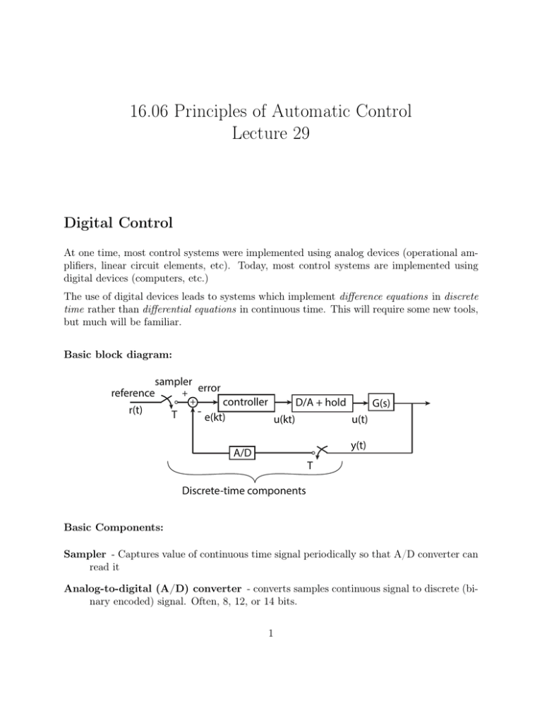
16.06 Principles of Automatic Control Lecture 29 Digital Control At one time, most control systems were implemented using analog devices (operational am­ plifiers, linear circuit elements, etc). Today, most control systems are implemented using digital devices (computers, etc.) The use of digital devices leads to systems which implement difference equations in discrete time rather than differential equations in continuous time. This will require some new tools, but much will be familiar. Basic block diagram: sampler + error reference r(t) + T controller - e(kt) D/A + hold u(kt) G(s) u(t) y(t) A/D T Discrete-time components Basic Components: Sampler - Captures value of continuous time signal periodically so that A/D converter can read it Analog-to-digital (A/D) converter - converts samples continuous signal to discrete (bi­ nary encoded) signal. Often, 8, 12, or 14 bits. 1 Controller - Implemented on a computer, which implements a difference equation, much as a continuous-time controller is an implementation of a differential equation on analog components. Digital-to-analog (D/A) converter - Converts a binary word to an analog signal. Zero Order Hold - Holds a constant value analog signal for one period. Discrete Time Control Time line Samples values of r, y converted to digital values Digital value of u converted to analog signal Control Computer calculates next value of u kT Control Computer performs other tasks kT+δ (k+1)T If the control computer is dedicated to a single task, then T is made as short as possible, and δ “ T. If the computer has many tasks, then T is longer, and δ ! T . In that case, can take δ “ 0. Of course, can have anything in between. For our purposes, we will assume one of the extremes, i.e., either δ “ 0, or δ “ T. Of course, can generalize to other cases. Analysis of Discrete Systems. Our system is a sampled-data system, meaning that it contains both discrete and continuous signals. However, we can treat it as a discrete system, by treating the dynamics from vpkT q to ypkT q as discrete. Discrete systems are a lot like continuous systems - they have step responses, pulse (not impulse) responses, and transfer functions. The counterpart of the Laplace Transform is the Z-Transform. Z-Transform The Z-transform of a sequence f rks is given by 2 F pzq “ Z rf rkss “ ÿ 8 ´k ´8 f rksz Note: I am using the bilateral transform. For every interesting property that you learned for the Laplace transforms, there is a corre­ sponding z-transform property. For instance, Z rf rk ´ 1ss “ 8 ÿ f rk ´ 1sz ´k k“´8 8 ÿ “ 1 f rk 1 sz ´pk `1q k1 “´8 ´1 “z F pzq (similar to Lrf9ptqs “ sF psq ) Using this property, can always differentiate equations. E.g., yrks “ ´a1 yrk ´ 1s ´ a2 yrk ´ 2s ` b0 urks ` b1 urk ´ 1s ` b2 urk ´ 2s Z-transform both sized to obtain Y psq “ p´a1 z ´1 ´ a2 z ´2 qY pzq ` pb0 ` b1 z ´1 ` b2 z ´2 qU pzq So the transfer function from u to y is Y pzq b0 ` b1 z ´1 ` b2 z ´2 “ U pzq 1 ` a1 z ´1 ` b2 z ´2 b0 z 2 ` b1 z ` b2 “ 2 z ` a1 z ` a2 Some Select Transforms 3 # 1, k“0 δrks “ 0, 1, ô z ´k0 ô z z´1 , ô z z´α1 , ô z z´e´aT kě0 σrks “ 0, |z| ą 1 kă0 σrksαk σrkse´akT 1 k‰0 δrk ´ k0 s # ô ` 1 s`a ˘ 4 |z| ą |α| MIT OpenCourseWare http://ocw.mit.edu 16.06 Principles of Automatic Control Fall 2012 For information about citing these materials or our Terms of Use, visit: http://ocw.mit.edu/terms.
