Session : Electrodynamic Tethers
advertisement

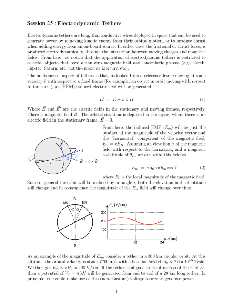
Session : Electrodynamic Tethers Electrodynamic tethers are long, thin conductive wires deployed in space that can be used to generate power by removing kinetic energy from their orbital motion, or to produce thrust when adding energy from an on-board source. In either case, the frictional or thrust force, is produced electrodynamically, through the interaction between moving charges and magnetic fields. From here, we notice that the application of electrodynamic tethers is restricted to celestial objects that have a non-zero magnetic field and ionospheric plasma (e.g., Earth, Jupiter, Saturn, etc, not the moon or Mercury, etc). The fundamental aspect of tethers is that, as looked from a reference frame moving at some velocity Ev with respect to a fixed frame (for example, an object in orbit moving with respect to the earth), an (EFM) induced electric field will be generated, E' = E E + Ev × B E E (1) E and E E ' are the electric fields in the stationary and moving frames, respectively. Where E E . The orbital situation is depicted in the figure, where there is no There is magnetic field B E = 0. electric field in the stationary frame, E From here, the induced EMF (Em ) will be just the product of the magnitude of the velocity vector and the “horizontal” component of the magnetic field, Em = vBH . Assuming an elevation β of the magnetic field with respect to the horizontal, and a magnetic co-latitude of θm , we can write this field as, Em = vB0 sin θm cos β (2) where B0 is the local magnitude of the magnetic field. Since in general the orbit will be inclined by an angle i, both the elevation and col-latitude will change and in consequence the magnitude of the Em field will change over time. N Em ( V km ) MN MN α α 300 i 200 100 12 S 24 t ( hrs ) As an example of the magnitude of Em , consider a tether in a 300 km circular orbit. At this altitude, the orbital velocity is about 7700 m/s with a baseline field of B0 ∼ 2.6 × 10⁻⁵ Tesla. E ', We then get Em ∼ vB0 ≈ 200 V/km. If the tether is aligned in the direction of the field E then a potential of Vm = 4 kV will be generated from end to end of a 20 km long tether. In principle, one could make use of this (non-constant) voltage source to generate power. 1 Tethers as Power Generators In this case, we have a spacecraft deploying an insulated tether “upwards” as shown in the figure. We assume the tether moves with a velocity Ev under a perpendicular magnetic field E . The tether has length e and a corresponding resistance RT . B e− ΔVA anode C VS φ plasm RT I a φ tether Em Em RL ΔVA ΔVC VL cathode e− As the tether moves, we have a field Em = vB that will generate an “open circuit” voltage Voc = vBe. If there is a load resistance RL in series, the a (positive) current will flow, as ionospheric electrons are collected on an exposed anode at the top of the tether, Voc − ΔV RT + RL I = (3) where ΔV is the (relatively small) total potential drop due to plasma sheaths at the anode and cathode. To complete the circuit, a cathode releases the electrons at the bottom of the tether. Given this current flow, electrical power will be generated at the load, 2 P = I RL = Voc − ΔV RT + RL 2 RL (4) We observe that the generated power is both zero when the load resistance is either zero or ∞. This means there is an optimum resistance that will yield maximum power. To find this, we differentiate Eq. (4) and set it to zero, therefore, Pmax = (Voc − ΔV )2 4RT which occurs when 2 RL = R T (5) The efficiency of this power-generating tether can be defined as, RL P I 2 RL = = ηg = IVoc RT + RL IVoc ∆V ΔV 1− Voc (6) We can easily verify that for maximum power generation, the efficiency is ηg ≈ 0.5. Ideally, we would like RL » RT for maximum efficiency, but then we get lower power. We can also verify that the input power IVoc is identical to the rate of change of the elec­ trodynamic drag work (force FE , force density fE), Ẇ = FE · Ev = � � fE · Ev dV = E · Ev dV = IBev = IEm e = IVoc Ej × B (7) Tethers as Thrusters Now, we have a spacecraft that deploys the tether “downwards”. In this case, the anode at the bottom collects electrons from the ionosphere. The Em field will point also upwards, however, we now have an on-board power supply that forces the net (positive) current in the opposite direction, as shown. e− e− ΔVC cathode ΔVA anode VS VS I a φ plasm RT φ tether RT I Em ΔVA RL V cathode anode e− e− Instead of removing energy from the orbit, this configuration will add energy, as the force E points in the direction of the velocity vector Ev , density fE = Ej × B FE = � Ev fE dV = IBe v With the current give by, 3 (8) I = Vs − ΔV − Em e RT (9) We could also write the magnitude of this force (thrust) as, F = ˙ IBve IEm e W = = v v v (10) Therefore, the rate of work added to the orbit is, Ẇ = F v (11) The efficiency of the tether as a thruster is, ηt = Voc Ẇ IEm e = = <1 IVs Vs IVs (12) It is then possible to use a tether both as a generator and a propellant-less thruster. In fact, since the tether can be used as a generator, an interesting question would be: what is the tether efficiency compared against a fuel cell? Fuel cells make use of some consumable (like propellant) to produce electric power. As an exercise, calculate the efficiency of a tether producing power when its drag is compensated by a thruster consuming propellant. This is a tether working as a fuel cell. Tether Dynamics As we have seen, it is important that the tether is oriented along the radial vector in its orbit for it to be used as an electrodynamic generator or thruster. F θ T θ ℓ × ℓ2 = ℓ × cm cm T ℓ1 = ℓ m1 m m2 m F We need to analyze the tether dynamics to verify that such alignment can be achieved without the use of complicated active control. 4 Referring to the schematic, we have a mass-less tether of length ` = `1 + `2 with two point masses at its ends, such that m1 + m2 = m. Let us analyze the dynamics of m2 , assuming that the center of mass (cm) is orbiting at a radius R. There will be a centrifugal force acting on m2 given by, m2 v 2 = R + `2 cos θ m2 v 2 `2 R 1 + cos θ R (13) which is balanced by a gravitational force, m2 µ = (R + `2 cos θ)2 m2 µ R2 `2 1 + cos θ R 2 (14) In addition, the orbital velocity is, `2 v = ΩR 1 + cos θ R (15) p and since µ/R = RΩ, then µ = R3 Ω2 . The net (upwards) force acting on m2 is the difference between these two forces, Fnet `2 1 = m2 Ω R 1 + cos θ − m2 Ω2 R 2 R `2 1 + cos θ R 2 (16) Even for a long wire, we have `2 R, therefore we can approximate, 1 1+ `2 cos θ R 2 ≈ 1 − 2 `2 cos θ R the net force on m2 is then, Fnet = 3m2 `2 Ω2 cos θ = 3 m1 m2 ` Ω2 cos θ m (17) The projection of this force on the direction of the wire is the tension, T = F cos θ (18) The tension on a 20 km tether for a mass of 100 kg would be 7.4 N, which is not a strong force enabling the use of light and thin wires. The projection of the net force in the orthogonal direction generates a torque, τ = −F ` sin θ and for small θ, 5 τ = −3 m1 m2 2 2 `Ωθ m (19) It is the clear that the gravity gradient force gives a torque that goes in the opposite direction to the tether defection from the vertical and therefore the it tends to stabilize the tether in the direction favorable for its use as electrodynamic actuator. Given its moment of inertia J, the tether rotational dynamics are described by, J dω = τ dt J = m1 e12 + m2 e22 = where m1 m2 2 e m (20) Combining Eq. (19) and Eq. (20), we get, θ¨ + 3 Ω2 θ = 0 (21) which means the tether will oscillate at a frequency, fω = √ 3Ω (22) For example, at 500 km altitude, we have Ω ≈ 10−3 rad/s, which corresponds to an orbital period of 94 minutes. The corresponding oscillation time for the tether would then be 54 minutes, which means we have a “lazy” oscillation. The dynamic analysis in the off-plane direction is somewhat more complicated, but yields an oscillation frequency in the same order, 2Ω. 6 MIT OpenCourseWare http://ocw.mit.edu 16.522 Space Propulsion Spring 2015 For information about citing these materials or our Terms of Use, visit: http://ocw.mit.edu/terms.


