L Fast liquid-crystal elastomer swims into the dark LETTERS
advertisement
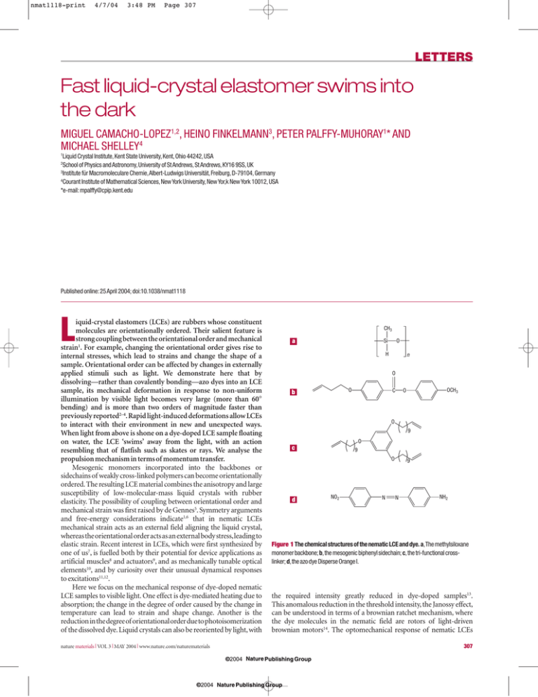
nmat1118-print 4/7/04 3:48 PM Page 307 LETTERS Fast liquid-crystal elastomer swims into the dark MIGUEL CAMACHO-LOPEZ1,2, HEINO FINKELMANN3, PETER PALFFY-MUHORAY1* AND MICHAEL SHELLEY4 1 Liquid Crystal Institute, Kent State University, Kent, Ohio 44242, USA School of Physics and Astronomy, University of St Andrews, St Andrews, KY16 9SS, UK 3 Institute für Macromoleculare Chemie,Albert-Ludwigs Universität, Freiburg, D-79104, Germany 4 Courant Institute of Mathematical Sciences, New York University, New Yor,k New York 10012, USA *e-mail: mpalffy@cpip.kent.edu 2 Published online: 25 April 2004; doi:10.1038/nmat1118 L iquid-crystal elastomers (LCEs) are rubbers whose constituent molecules are orientationally ordered. Their salient feature is strong coupling between the orientational order and mechanical strain1. For example, changing the orientational order gives rise to internal stresses, which lead to strains and change the shape of a sample. Orientational order can be affected by changes in externally applied stimuli such as light. We demonstrate here that by dissolving—rather than covalently bonding—azo dyes into an LCE sample, its mechanical deformation in response to non-uniform illumination by visible light becomes very large (more than 60° bending) and is more than two orders of magnitude faster than previously reported2–4. Rapid light-induced deformations allow LCEs to interact with their environment in new and unexpected ways. When light from above is shone on a dye-doped LCE sample floating on water, the LCE ‘swims’ away from the light, with an action resembling that of flatfish such as skates or rays. We analyse the propulsion mechanism in terms of momentum transfer. Mesogenic monomers incorporated into the backbones or sidechains of weakly cross-linked polymers can become orientationally ordered. The resulting LCE material combines the anisotropy and large susceptibility of low-molecular-mass liquid crystals with rubber elasticity. The possibility of coupling between orientational order and mechanical strain was first raised by de Gennes5. Symmetry arguments and free-energy considerations indicate1,6 that in nematic LCEs mechanical strain acts as an external field aligning the liquid crystal, whereas the orientational order acts as an external body stress,leading to elastic strain. Recent interest in LCEs, which were first synthesized by one of us7, is fuelled both by their potential for device applications as artificial muscles8 and actuators9, and as mechanically tunable optical elements10, and by curiosity over their unusual dynamical responses to excitations11,12. Here we focus on the mechanical response of dye-doped nematic LCE samples to visible light. One effect is dye-mediated heating due to absorption; the change in the degree of order caused by the change in temperature can lead to strain and shape change. Another is the reduction in the degree of orientational order due to photoisomerization of the dissolved dye. Liquid crystals can also be reoriented by light, with CH3 a Si O H n O O b C OCH3 O O 9 O c 9 O d NO2 N 9 N NH2 Figure 1 The chemical structures of the nematic LCE and dye. a,The methylsiloxane monomer backbone; b,the mesogenic biphenyl sidechain; c,the tri-functional crosslinker; d,the azo dye Disperse Orange I. the required intensity greatly reduced in dye-doped samples13. This anomalous reduction in the threshold intensity, the Janossy effect, can be understood in terms of a brownian ratchet mechanism, where the dye molecules in the nematic field are rotors of light-driven brownian motors14. The optomechanical response of nematic LCEs nature materials | VOL 3 | MAY 2004 | www.nature.com/naturematerials 307 ©2004 Nature Publishing Group ©2004 Nature Publishing Group nmat1118-print 4/7/04 3:48 PM Page 308 LETTERS a a 2 mm 2 mm t=0 5.0 5.5 6.0 6.5 7.0 9.0 s b t=0 t = 80 ms 1.2 1 1 2.5 τ = 75 ms log (Force) 0 2.0 Force (mN) Displacement (cm) b 1.5 –1 Clean surface Soap on surface 0.8 0.6 0.4 –2 0.2 –3 50 1.0 100 200 150 Time (ms) 250 300 0 0 200 400 600 800 1,000 Time (ms) 1,200 1,400 1,600 1,800 0.5 c 0.0 0 100 200 Time (ms) 300 400 500 t=0 Figure 2 The optomechanical response of an LCE sample.a,Two frames from a video clip recording the bending and relaxation dynamics of the sample.Left figure:a dye-doped LCE sample of dimensions 5 mm × 5 mm × 0.32 mm anchored at one end is illuminated from above for 60 ms by green light at 514 nm from a continuous-wave argon-ion laser (600 mW) with a 3-mm beam waist (full-width at half-maximum).The gaussian beam is approximately centred on the sample.Right figure:the sample about 80 ms after onset of illumination.The sample has reached a bend angle of roughly 45°.The dashed white line graphically superimposed on the sample edge in the video image shows the orientation of the nematic director,and bending of the material due to contraction along the director. b,Graph of the dynamics of force produced by the sample on and after illumination for 60 ms.The free end of the sample was held in place and prevented from bending by the needle arm of an Entran load sensor measuring the force.The rise time of 20 ms is determined by fitting the increasing part of the force curve to an exponential function describing the approach to saturation.The inset shows the logarithm of the measured force after illumination is removed (60 ms after onset).This reveals a clear exponential relaxation back to the rest state.The linear fit shows the relaxation time to be 75 ms. with covalently bonded azo dyes has been studied2,3. These materials showed large isochoric contraction (by more than 20% of their original length) when irradiated with ultraviolet light, with relaxation times of the order of one hour. Our monodomain LCE samples consist of a poly(methylsiloxane) backbone with attached mesogenic biphenyl side-chain units (Fig. 1). Using a tri-functional cross-linker, samples under preparation are first weakly cross-linked, then stretched unidirectionally to align the mesogens and establish nematic order, and then finally fully cross-linked to form a transparent birefringent monodomain15. The alignment direction can be determined from the orientation of the principal optical axes. To retain high orientational mobility in our samples, the azo dye Disperse Orange I was dissolved (rather than functionalized as in previous work2,3) into the network. To accomplish this, nematic LCE samples were swollen with toluene in which the dye 4 6 10 s Figure 3 The interaction of a dye-doped LCE sample with a liquid.A 5-mm-diameter disk of dye-doped LCE sample (0.32 mm thick) is floating nearly motionless on the surface of a water reservoir (roughly 2 cm in depth) when illuminated from above by an argon-ion laser with peak intensity of 1.1 W cm–2 and beam waist of 3 mm.a,A series of video frames as the LCE sample moves away from the area of sustained illumination,seen as the bright disk in the centre of each photo.b,The measured displacement of the LCE sample centre from its initial rest position as a function of time from onset of illumination.As the locomotion is essentially the same in the presence of a surfactant soap (green) as on pure water (red),the motion does not originate in surface-tension effects.The displacement scales nearly linearly with laser power.c,Irregular rectangular LCE sample floating on ethylene glycol first folds then swims away when illuminated.The nematic director is along the edge on lower left. had been dissolved; the toluene was subsequently removed through evaporation in a vacuum oven.The concentration of the dye remaining in the samples,assumed to be uniform and estimated from absorptivity measurements, was 0.1 wt%. The density of our samples was 0.973 g cm–3, and the thickness of the undeformed LCE films was 0.32 mm. Disperse Orange I molecules are known to align with the director in nematic liquid crystals. In our samples, we observed a broad absorption peak whose amplitude was strongly polarizationdependent, with an absorption maximum at λM = 495 nm. We illuminated our dye-doped LCE samples by green light at λ = 514 nm from a continuous-wave Ar+ ion laser. For samples of size 5 mm × 5 mm × 0.32 mm supported at one end (Fig. 2), the dominant effect is a large and rapid light-induced bend deformation (>45° bend angle after illumination for 60ms at 600mW).The axis of the cylindrical bend is parallel to the sample surface and perpendicular to the nematic nature materials | VOL 3 | MAY 2004 | www.nature.com/naturematerials 308 ©2004 Nature Publishing Group ©2004 Nature Publishing Group nmat1118-print 4/7/04 3:48 PM Page 309 LETTERS director,whose direction in the sample is known.We measured the force developed by our dye-doped samples when prevented from bending and found remarkably fast response times, with a rise time of 20 ms at 600 mW and a relaxation time of 75 ms. These times were determined from the measured exponential approach to saturation, and the measured exponential decay after cessation of illumination. The size of deformation and its timescales are also power-dependent with more rapid onset to larger deformation with increased power (for example, a bend angle of 67°after irradiation for 60 ms at 1.3 W). The observed bending is consistent with a rapid material contraction along the nematic director at the irradiated surface. This contraction is apparently volume-conserving as it is accompanied by an expansion (small, given the aspect ratio of the sample) in the orthogonal direction. The contraction is consistent with decreased orientational order at the surface,relative to the anisotropically ordered rest state,which could lead to the observed material strains.Plausible candidate mechanisms for this effect are laser heating by linear absorption and the reduction of orientational order by photoisomerization of the dye.Direct and indirect optical torques may also contribute.We are currently conducting further experimental and modelling studies to identify the salient mechanisms. Finally, to see how dye-doped LCE materials might interact with their environment, we have studied their interaction with fluids by illuminating from above LCE samples floating on water. We find, astonishingly,that samples will swim away from the light.The direction of the observed motion,at least initially,is perpendicular to the nematic director. Figure 3a shows video frames, and Fig. 3b shows the displacement, of a 5-mm-diameter LCE disk under illumination with peak intensity of 1.1 W cm–2 from the argon-ion laser. This swimming behaviour is remarkable, because no linear momentum is transferred from the radiation field to the sample in the horizontal direction of motion. The system is therefore a motor, where motion is caused by the transfer of energy, but not momentum, to the system. We propose the following explanation. Regarding the energetics, we note that illumination causes the flat sample to change shape and to adopt a more compact, bent, configuration. On the cessation of illumination, the sample unbends to resume its original flat shape; it is capable of doing work in this process. As the elastic energy of a bent elastic sheet is (1/24)Y(d 3/R2)A,where Y is Young’s modulus, R is the radius of curvature, d is the thickness and A is the area, a crude estimate of the energy stored in the bent sample is ∼10 nJ. When the sample bends, it also sinks lower in the water. As the potential energy of the water supporting the sample is Mgh, where M is the mass of the sample, g is the acceleration due to gravity and h is the average depth of the sample under water,this shape change increases the potential energy of the water. A simple estimate of the potential energy, assuming a spherical deformation with radius of curvature equal to the disk diameter,gives 8nJ.Energy for the swimming,provided by the light, is therefore stored both in the LCE and in the water. Because the sample shape depends on illumination that is localized, the sample shape, and hence the potential energy of the system,is a function of position.As the sample moves away from the light, it relaxes, regains its extended configuration and makes available stored potential energy to do work and to cause motion. If half of the stored energy provides the kinetic energy of motion and half is dissipated in viscous shear,and if half of the kinetic energy is imparted to the water and the other half to the disk, the corresponding disk velocity is ∼4 cm s–1. This is the same order of magnitude as the observed maximum velocity of 1.9 cm s–1.Estimates of the exponential growth and decay times of the velocity are similarly in crude agreement with observations. Regarding momentum transfer between the LCE sample and water during swimming, we conjecture the following mechanism for the propulsion. If the illuminating beam is centred on the disk, the disk contracts along the director (and expands in the other two directions to conserve volume) forming a saddle shape, as shown in Fig. 4. If the deformed disk is now slightly displaced, say by water or air convection, a b Light Light Force on LCE Force on water Figure 4 Illustration of the mechanism underlying the locomotion of the dyedoped LCE sample. a,A single video frame showing the shape deformation of an LCE sample immediately following illumination. Here the sample is supported by a pin in air and the image is recorded approximately along the nematic director.The illumination is centred on the pin. b, Illustration of how the sample shape changes and hence interacts with the fluid below it.The left figure shows the initial deformation of the sample on illumination.The black arrow shows the axis of the bend, which is orthogonal to the nematic director whose direction of alignment across the sample is shown as a dashed white curve.The right figure shows the motion of the sample as the centre of deformation moves back along the axis of the bend toward the light, and momentum is exchanged between the sample and the fluid. capillary waves or other noise, away from the laser spot, the shape will change again with the elevated ‘shoulders’ moving in the direction opposite to the displacement, towards the stationary laser spot. This motion will push the water under the shoulders in the same direction as the motion of the shoulders,in the direction opposite to the displacement, and, by Newton’s third law, water will in turn push the LCE sample in the direction of the original displacement.The force from the water will accelerate the sample away from the light, and lead to a further displacement in the same direction,resulting in yet greater force from the water. The original configuration with the illuminated sample under the beam is thus unstable; any in-plane perturbation in the sample position normal to the director gives rise to a force in the same direction,which,with increasing magnitude,will push the sample from under the illuminating beam. The exchange of momentum between water and object is the basis of rowing, which can be dominated by either inertial or viscous effects. The Reynolds number of the water,estimated from the size and speed of the LCE sample, is about 100, indicating that both inertial and viscous forces are significant. The shape-change dynamics, furthermore, is similar to a peristaltic pump; the pumping here develops as part of the intrinsic dynamics moving the system away from an unstable equilibrium. Pushing water backwards to move forwards is common in biological locomotion; indeed, our ‘swimming’ LCE sample closely resembles a flatfish,such as the atlantic stingray,which swims by passing nature materials | VOL 3 | MAY 2004 | www.nature.com/naturematerials 309 ©2004 Nature Publishing Group ©2004 Nature Publishing Group nmat1118-print 4/7/04 3:48 PM Page 310 LETTERS undulatory waves down the pectoral fins16. Similarly, water striders use depressions in the free surface of water as oars to ‘row’ across the surface17. We envisage similarly sustained but optically driven locomotion of an LCE sample by tracking and periodic illumination; other drive schemes (thermal, electrical, magnetic) that induce controlled shape changes may also be viable. Dye-doped nematic LCEs undergo large and rapid shape changes on illumination. Samples floating on water swim away from the light, because the compact deformed configuration increases the energy of the system. We conjecture that if the illuminated configuration was the extended non-compact shape,the samples could swim towards the light. Key to this process is the position-dependent shape change.The system is an unusual motor; the light source must supply not only energy,but also positional information, to bring about motion. Detailed modelling of the dynamics of this system,combining the statistical mechanics of LCE6 with the generalized hydrodynamics of viscoelastic solids18, is currently under way. Received 14 January 2004; accepted 18 March 2004; published 25 April 2004. References 1. de Gennes, P. G. Réflexions sur un type de polymères nématiques. C. R. Acad. Sci. Ser. B 281, 101–103 (1975). 2. Finkelmann, H., Nishikawa, E., Pereira, G. G. & Warner, M. A. New opto-mechanical effect in solids. Phys. Rev. Lett. 87, 015501 (2001). 3. Cviklinski, J., Tajbakhsh, A. R. & Terentjev, E. M. UV isomerisation in nematic elastomers as a route to photo-mechanical transducer. Eur. Phys. J. E 9, 427–434 (2002). 4. Yu, Y., Nakano, M. & Ikeda, T. Directed bending of a polymer film by light. Nature 425¸145 (2003). 5. de Gennes, P. G. Possibilities allowed by polymer reticulation in the presence of a liquid crystal. Phys. Lett. A 28, 725 (1969). 6. Warner, M. & Terentjev, E. M. Liquid Crystal Elastomers (Clarendon, Oxford, 2003). 7. Finkelmann, H., Kock, H. & Rehage, G. Investigations on LC polysiloxanes: 3. Liquid crystalline elastomers—a new type of liquid crystalline material. Makromol. Chem. Rapid Commun. 2, 317 (1981). 8. Shenoy, D. K., Thomsen, D. L., Srinivasan, A., Keller, P. & Ratna, B. R. Carbon coated liquid cystal elastomer film for artificial muscle applications. Sensors Actuators A 96, 184–188 (2002). 9. Courty, S., Mine, J., Tajbakhsh, A. R. & Terentjev, E. M. Nematic elastomers with aligned carbon nanotubes: New electromechanical actuators. Europhys. Lett. 64, 654–660 (2003). 10. Finkelmann, H., Kim, S. T., Munoz, A., Palffy-Muhoray, P. & Taheri, B. Tunable mirrorless lasing in cholesteric liquid crystalline elastomers. Adv. Mater. 13, 1069–1072 (2001). 11. Clarke, S. M., Tajbakhsh, A. R., Terentjev, E. M. & Warner, M. Anomalous viscoelastic response of nematic elastomers. Phys. Rev. Lett. 86, 4044–4047 (2001). 12. Terentjev, E. M., Hotta, S., Clarke, M. & Warner, M. Liquid crystalline elastomers: dynamics and relaxation of microstructure. Phil. Trans. R. Soc. Lond. A 361, 1–12 (2003). 13. Janossy, I., Lloyd, A. D. & Wherrett, B. S. Anomalous optical Freedericksz transition in an absorbing liquid crystal. Mol. Cryst. Liq. Cryst. 179, 1–12 (1990). 14. Palffy-Muhoray, P., Kosa, T. & E, W. Brownian motors in the photoalignment of liquid crystals. Appl. Phys. A 75, 293–300 (2002). 15. Kupfer, J. & Finkelmann, H. Liquid crystal elastomers: influence of the orientational distribution of the crosslinks on the phase behaviour and reorientation process. Macromol. Chem. Phys. 195, 1353–1367 (1994). 16. Rosenberger, L. J. Pectoral fin locomotion in batoid fishes: undulation versus oscillation. J. Exp. Biol. 204, 379–394 (2001). 17. Hu, D., Chan, B. & Bush, J. The hydrodynamics of water-strider locomotion. Nature 424, 663–666 (2003). 18. Temmen, H., Pleiner, H., Liu, M. & Brand, H. R. Convective nonlinearity in non-Newtonian Fluids. Phys. Rev. Lett. 84, 3228–3231 (2000). Acknowledgements This work was supported by the US National Science Foundation and the Department of Energy. We thank T. Toth-Katona for his help with Fig. 4a. Correspondence and requests for materials should be addressed to P.P.-M. Competing financial interests The authors declare that they have no competing financial interests. nature materials | VOL 3 | MAY 2004 | www.nature.com/naturematerials 310 ©2004 Nature Publishing Group ©2004 Nature Publishing Group
