Research Journal of Applied Sciences, Engineering and Technology 7(12): 2437-2440,... ISSN: 2040-7459; e-ISSN: 2040-7467
advertisement

Research Journal of Applied Sciences, Engineering and Technology 7(12): 2437-2440, 2014
ISSN: 2040-7459; e-ISSN: 2040-7467
© Maxwell Scientific Organization, 2014
Submitted: May 07, 2013
Accepted: June 15, 2013
Published: March 29, 2014
Design and Implementation of Smart Home Intranet Based on ZigBee
1
Yuanxin Lin, 2Rui Kong, 1Mingzhong Guan and 1Rongbin She
1
Electrical Information College,
2
College of Electrical and Information, Jinan University, Zhuhai, 519070, China
Abstract: The study has design and implementation of smart home intranet based on ZigBee. As the continuous
development of Internet of Things (IOT), life intelligent gradually. Therefore, designed of home intranet become the
inevitable trend of development. Therefore, the study is going to talk about an Intelligent Monitoring System based
on ZigBee which was designed by the author. The system uses a low-power-cost CC 2430 processor as central
controller, present a home gateway of wireless access scheme base on ZigBee wireless network. The touch screen
interface allows the ZigBee technology to achieve wireless monitoring of home device. Such as light, temperature,
humidity, fire alarm, curtain, smart socket and so on. At the end of the study it will give out the techniques and
implementation of the original system.
Keywords: Home device, home intranet, interface, wireless monitoring, ZigBee
INTRODUCTION
The study presents a home gateway of wireless
access scheme base on ZigBee wireless network
(Shouwei and Canyang, 2009). The user would control
nodes for sensor data and monitoring node equipment
real time through the interface.
Relative to the others wireless communication
standard, ZigBee protocol stack is very simple and low
requirements of the master controller. 8-bit processor
with 4 KB ROM and 64 KB RAM, etc., to meet the
minimum requirements, thereby reducing the cost of
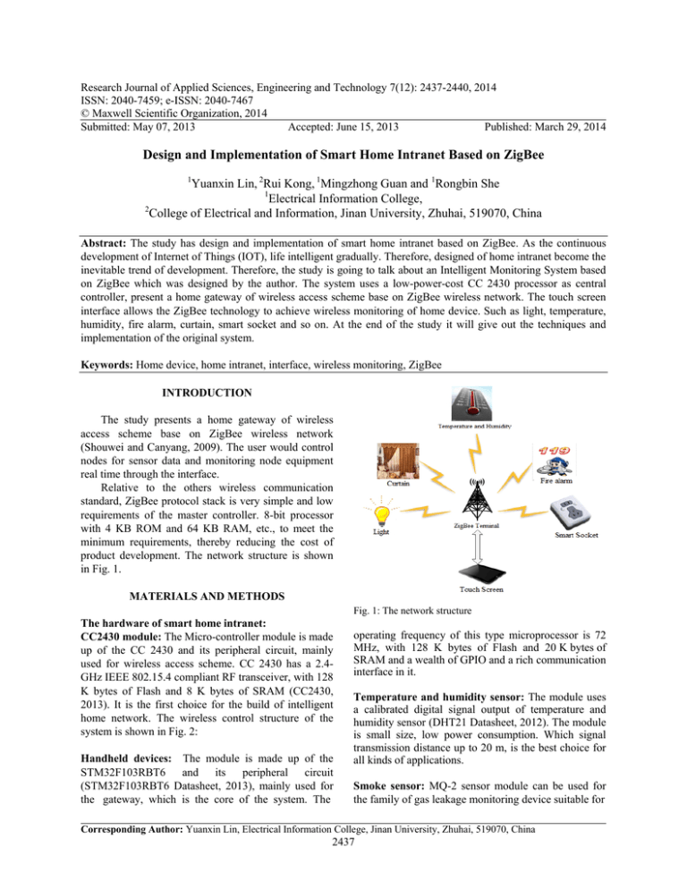
product development. The network structure is shown
in Fig. 1.
MATERIALS AND METHODS
Fig. 1: The network structure
The hardware of smart home intranet:
CC2430 module: The Micro-controller module is made
up of the CC 2430 and its peripheral circuit, mainly
used for wireless access scheme. CC 2430 has a 2.4GHz IEEE 802.15.4 compliant RF transceiver, with 128
K bytes of Flash and 8 K bytes of SRAM (CC2430,
2013). It is the first choice for the build of intelligent
home network. The wireless control structure of the
system is shown in Fig. 2:
Handheld devices: The module is made up of the
STM32F103RBT6 and its peripheral circuit
(STM32F103RBT6 Datasheet, 2013), mainly used for
the gateway, which is the core of the system. The
operating frequency of this type microprocessor is 72
MHz, with 128 K bytes of Flash and 20 K bytes of
SRAM and a wealth of GPIO and a rich communication
interface in it.
Temperature and humidity sensor: The module uses
a calibrated digital signal output of temperature and
humidity sensor (DHT21 Datasheet, 2012). The module
is small size, low power consumption. Which signal
transmission distance up to 20 m, is the best choice for
all kinds of applications.
Smoke sensor: MQ-2 sensor module can be used for
the family of gas leakage monitoring device suitable for
Corresponding Author: Yuanxin Lin, Electrical Information College, Jinan University, Zhuhai, 519070, China
2437
Res. J. Appl. Sci. Eng. Technol., 7(12): 2437-2440, 2014
life and other characteristics. The schematic diagram is
shown in Fig. 3.
Curtain control module: The curtain control module
L298N DC motor contains an internal 4-channel logical
drive circuit, which is a two-phase and four-phase
motor dedicated drive (L298N Datasheet, 2013). We
change chip level through I/O input, to control the
motor rotating and stop. The schematic diagram is
shown in Fig. 4.
Fig. 2: Wireless control structure of the system
LPG, butane, propane, methane, alcohol, smoke, (MQ-2
Datasheet, 2013). The module has a high stability, long
Smart socket: The smart socket with 5 V Relay
Module, using Opto-isolated circuit improve safety and
using low level interrupt to turn on or off home device
of 220 V (Relay Datasheet, 2012). The schematic
diagram is shown in Fig. 5.
Fig. 3: The schematic diagram of smoke sensor
Fig. 4: The schematic diagram of curtain control module
2438
Res. J. Appl. Sci. Eng. Technol., 7(12): 2437-2440, 2014
Fig. 5: The schematic diagram of smart socket
Fig. 6: ZigBee protocol stack structure
Home node control: Temperature and humidity
sensors, mainly through the temperature reporting
functions as well as the humidity reporting function, to
achieve the home environment temperature and
humidity detection, as follows:
pExTemp [0] = EXTEMP_REPORT;
myApp_ReadExTemperature ();
osal_memcpy (pExTemp+1, ch, 6);
zb_SendDataRequest (0xFFFE,
SENSOR_REPORT_CMD_ID, 7, pExTemp, 0,
AF_ACK_REQUEST, 0);
}
if (event == MY_REPORT_RH_EVT) // humidity
reporting function
{
pExTemp [0] = RH_REPORT;
myApp_ReadR_Humidity ();
osal_memcpy (pExTemp+1, sh, 6);
zb_SendDataRequest (0xFFFE,
SENSOR_REPORT_CMD_ID, 7, pExTemp, 0,
AF_ACK_REQUEST, 0);
}
if (event == MY_REPORT_EXTEMP_EVT) //
temperature reporting functions
{
Smoke sensor, primarily through the interrupt
function, to achieve real-time monitoring of the smoke
of the home environment, as follows:
THE SOFTWARE OF SMART
HOME INTRANET
The wireless network protocols ZigBee: ZigBee
protocol uses the IEEE 802.15.4 defines the Physical
Layer (PHY) and the media Media Access layer (MAC)
(Shouwei and Canyang, 2009). And on this basis to
define the architecture of the Network layer (NWK) and
Application Layer (APL) (Shouwei and Canyang,
2009). ZigBee protocol stack structure is shown in
Fig. 6.
2439
Res. J. Appl. Sci. Eng. Technol., 7(12): 2437-2440, 2014
Curtain control, mainly through the motor stop
function, open function and close function, to open and
close the curtains, as follows:
if (event == MY_STOP_MOTO_EVT) // motor
stop function
{
pData [0] = MOTO_REPORT;
pData [1] = 5;
zb_SendDataRequest (0xFFFE,
SENSOR_REPORT_CMD_ID, 7, pData, 0,
AF_ACK_REQUEST, 0);
}
Fig. 7: Interface display of the touch screen
RESULTS AND DISCUSSION
There are four parts of the test: remote terminal test
of the touch screen and test of ZigBee wireless home
node. System test are shown in Fig. 7 to 9.
CONCLUSION
This study designs and implements an intelligent
monitoring system based on ZigBee. Achieved the
ZigBee short-range wireless sensor networks connect
with terminal. The thesis also presented the structure of
hardware based on the ZigBee protocol, handheld
devices, temperature and humidity sensor, smoke
sensor, curtain control module, smart socket. This
System is low-cost, high-safety, energy-efficient and
eco-friendly so that it gives new development direction
of intelligent household system.
Fig. 8: Wireless home node 1
REFERENCES
Fig. 9: Wireless home node 2
if (keys and HAL_KEY_SW_6) // the interrupt function
of the smoke
{
osal_start_timerEx (sapi_TaskID, Interrupt0, my
Interrupt
Report
Period);
HalLedSet
(HAL_LED_1, HAL_LED_MODE_BLINK);
}
CC2430, 2013. Retrieve from: http:// baike. baidu. com/
view/ 1735618.htm, (Accessed on: January 25,
2013).
DHT21 Datasheet, 2012. Retrieve from: http:// wenku.
baidu. com/ view/ 77 be 190 a 79563 c1 ec 5 da
7103. html, (Accessed on: Dec. 12, 2012).
L298N Datasheet, 2013. Retrieve from: http://wenku.
baidu.com/view/e25f441b6bd97f192279e953.html,
(Accessed on: January 24, 2013).
MQ-2 Datasheet, 2013. Retrieve from: http://wenku.
baidu.com/view/903f55a4b0717fd5360cdcc2.html,
(Accessed on: February 07, 2013).
Relay Datasheet, 2012. Retrieve from: http://wenku.
baidu.com/view/de976bf2f61fb7360b4c6552.html,
(Accessed on: November 14, 2012).
Shouwei, G. and W. Canyang, 2009. ZigBee
Technology Practice Tutorial. Beijing University
of Aeronautics and Astronautics Press, China.
STM32F103RBT6 Datasheet, 2013. Retrieve from:
http://wenku.baidu.com/view/210f617931b765ce0
508141b.html (Accessed on: March 25, 2013).
2440


