Performance evaluation of OFDMA system of LTE in terms of PAPR
advertisement
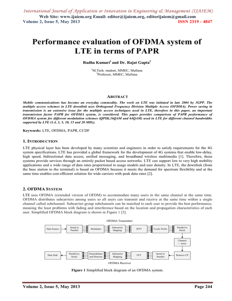
International Journal of Application or Innovation in Engineering & Management (IJAIEM) Web Site: www.ijaiem.org Email: editor@ijaiem.org, editorijaiem@gmail.com Volume 2, Issue 5, May 2013 ISSN 2319 - 4847 Performance evaluation of OFDMA system of LTE in terms of PAPR Radha Kumari1 and Dr. Rajat Gupta2 1 M.Tech. student, MMEC, Mullana 2 Professor, MMEC, Mullana ABSTRACT Mobile communications has become an everyday commodity. The work on LTE was initiated in late 2004 by 3GPP. The multiple access schemes in LTE downlink uses Orthogonal Frequency Division Multiple Access (OFDMA). Power saving in transmission is an extensive issue for the multiple access techniques used in LTE, therefore in this paper, an important transmission factor PAPR for OFDMA system, is considered. This paper provides comparison of PAPR performance of OFDMA system for different modulation schemes (QPSK,16QAM and 64QAM) used in LTE for different channel bandwidths supported by LTE (1.4, 3, 5, 10, 15 and 20 MHz). Keywords: LTE, OFDMA, PAPR, CCDF 1. INTRODUCTION LTE physical layer has been developed by many scientists and engineers in order to satisfy requirements for the 4G system specifications. LTE has provided a global framework for the development of 4G systems that enable low-delay, high speed, bidirectional data access, unified messaging, and broadband wireless multimedia [1]. Therefore, these systems provide services through an entirely packet based access networks. LTE can support low to very high mobility applications and a wide range of data rates proportional to usage models and user density. In LTE, the downlink (from the base station to the terminal) is based on OFDMA because it meets the demand for spectrum flexibility and at the same time enables cost-efficient solution for wide carriers with peak data rates [2]. 2. OFDMA SYSTEM LTE uses OFDMA (extended version of OFDM) to accommodate many users in the same channel at the same time. OFDMA distributes subcarriers among users so all users can transmit and receive at the same time within a single channel called subchannel. Subcarrier-group subchannels can be matched to each user to provide the best performance, meaning the least problems with fading and interference based on the location and propagation characteristics of each user. Simplified OFDMA block diagram is shown in Figure 1 [3]. OFDMA Transmitter Data Source Serial to Parallel Modulator Subcarrier Mapping IFFT Cyclic Prefix Parallel to Serial Channel + noise Data Sink Parallel to Serial Demodulator and Detector Subcarrier Mapping FFT Serial to Parallel Remove CP OFDMA Receiver Figure 1 Simplified block diagram of an OFDMA system. Volume 2, Issue 5, May 2013 Page 244 International Journal of Application or Innovation in Engineering & Management (IJAIEM) Web Site: www.ijaiem.org Email: editor@ijaiem.org, editorijaiem@gmail.com Volume 2, Issue 5, May 2013 ISSN 2319 - 4847 3. PAPR Power saving in transmission is an extensive issue for the multiple access techniques used in LTE, therefore it is to be considered here, as an important transmission factor known as PAPR for OFDMA system. Due to the presence of large number of independently modulated sub-carriers in an OFDMA system, the peak value of system can become very high as compared to the average value of whole system [4]. This ratio of peak power to average power value is termed Peakto-Average Power Ratio. A large PAPR in OFDMA system increases the complexity of analog–to–digital and digital– to–analog converter, and this reduces the efficiency of radio frequency (RF) power amplifier. Mathematically, the peak to average power ratio [5] for a signal x(t) is defined as, PAPR max x t x * t Ex t x * t (1) where, * corresponds to the conjugate operator. Expressing in decibels [5], PAPRdB 10 log 10 PAPR (2) PAPR, in quantitative terms, is usually expressed in terms of Complementary Cumulative Distribution Function (CCDF) and is mathematically given by [5]: (3) PAPR0 N PPAPR PAPR0 1 1 e Where, PAPR0 is the clipping level. This equation can also be read as the probability that the PAPR of a symbol block exceeds some clip level PAPR0. 4. RESULTS AND DISCUSSION LTE supports scalable channel bandwidths, such as; 1.4, 3, 5, 10, 15 and 20MHz, and modulation schemes QPSK, 16QAM and 64QAM. Thus, performance of OFDMA system for the above mentioned modulation schemes and bandwidths, in terms of PAPR using CCDF plots, are taken into consideration. High value of PAPR is undesirable, for better performance. CCDF plots of OFDMA system for different channel bandwidths and modulation schemes are depicted from Figures 2 to 7. i. CCDF plot for 1.4MHz is shown in Figure 2 below. Figure 2 CCDF plot of OFDMA at 1.4MHz. As can be seen from Figure 2, PAPR for 64QAM is less for 1.4MHz channel bandwidth, thus it will give better performance in this channel bandwidth. ii. Figure 3 shows CCDF plot for 3MHz bandwidth. Volume 2, Issue 5, May 2013 Page 245 International Journal of Application or Innovation in Engineering & Management (IJAIEM) Web Site: www.ijaiem.org Email: editor@ijaiem.org, editorijaiem@gmail.com Volume 2, Issue 5, May 2013 ISSN 2319 - 4847 Figure 3 CCDF plot of OFDMA at 3MHz. From Figure 3, it is seen that 64QAM is better option at 3MHz bandwidth due to less PAPR. iii. CCDF plot for 5MHz is depicted in Figure 4. Figure 4 CCDF plot of OFDMA at 5MHz. As shown in Figure 4, it is clear that 64QAM is again shows the better option at 5MHz. iv. CCDF plot for 10MHz is shown in Figure 5. Figure 5 CCDF plot of OFDMA at 10MHz. Volume 2, Issue 5, May 2013 Page 246 International Journal of Application or Innovation in Engineering & Management (IJAIEM) Web Site: www.ijaiem.org Email: editor@ijaiem.org, editorijaiem@gmail.com Volume 2, Issue 5, May 2013 ISSN 2319 - 4847 From Figure 5, it can be seen that 64QAM is the better option at 10MHz bandwidth also. v. Figure 6 shows CCDF plot of OFDMA at 15MHz. Figure 6 CCDF plot of OFDMA at 15MHz. From Figure 6, it is clear that 64 QAM has better performance at 15MHz in terms of PAPR. vi. CCDF plot for 20MHz is shown in Figure 7 below. Figure 7 CCDF plot of OFDMA for 20MHz. Figure 7 shows 64QAM modulation scheme has less PAPR value, thus, it is again the better option among QPSK and 16QAM. 5. CONCLUSION The performance of OFDMA system in LTE in terms of PAPR is described using CCDF plots for different modulation schemes in all supported channel bandwidths of LTE. From the simulation of CCDF plots, it is clear that 64QAM is the better option among the QPSK and 16QAM. REFERENCES [1.] 3GPP, 3rd generation partnership project, Technical specification group radio access network, Physical Channels and Modulation (Release 8), 3GPP TS 36.211. [2.] T. Jiang and Y. Wu, “An Overview: Peak-to-Average Power Ratio Reduction Techniques for OFDM Signals,” IEEE Transactions on Broadcasting, vol. 54, no. 2, June 2008. [3.] C. P. Li, S. H. Wang, and C. L. Wang, “Novel Low-Complexity SLM Schemes for PAPR Reduction in OFDM Systems,” IEEE Transactions on Signal Processing. vol. 58, no. 5, pp. 2916-2921, 2010. Volume 2, Issue 5, May 2013 Page 247 International Journal of Application or Innovation in Engineering & Management (IJAIEM) Web Site: www.ijaiem.org Email: editor@ijaiem.org, editorijaiem@gmail.com Volume 2, Issue 5, May 2013 ISSN 2319 - 4847 [4.] S.H. Han, and J.H. Lee, “An overview of peak to average power ratio reduction techniques for multicarrier transmission,” IEEE Wireless Commun. vol. 12, no. 2, pp. 56-65, 2005. [5.] Qualcomm, “Description and Simulations of Interference Management Technique for OFDMA Based E-UTRA Downlink Evaluation,” 3GPP RAN WG1 #42, London, UK. 2005. AUTHORS 1) Radha Kumari is M.Tech. student of ECE department in MMEC, Mullana. 2) Dr. Rajat Gupta has done B.Tech. in electronics from Govt. Engg. College (Pb) in 1995, M.Tech. from NIT in 1998 and Ph.D. in Electronics. Presently he is working as Professor in ECE department in MMEC, Mullana. Volume 2, Issue 5, May 2013 Page 248
