Certus Optic NanoScanTechnology Basic Datasheet reasoned innovations
advertisement
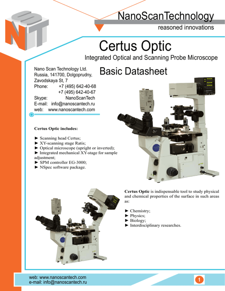
NanoScanTechnology reasoned innovations Certus Optic Integrated Optical and Scanning Probe Microscope Nano Scan Technology Ltd. Russia, 141700, Dolgoprudny, Zavodskaya St, 7 Phone: +7 (495) 642-40-68 +7 (495) 642-40-67 Skype: NanoScanTech E-mail: info@nanoscantech.ru web: www.nanoscantech.com Basic Datasheet Certus Optic includes: ► Scanning head Certus; ► XY-scanning stage Ratis; ► Optical microscope (upright or inverted); ► Integrated mechanical XY-stage for sample adjustment; ► SPM controller EG-3000; ► NSpec software package. Certus Optic is indispensable tool to study physical and chemical properties of the surface in such areas as: ► Chemistry; ► Physics; ► Biology; ► Interdisciplinary researches. web: www.nanoscantech.com e-mail: info@nanoscantech.ru 1 Advantages of Certus Optic: ► Scanning stage Ratis can position the sample with sub-nanometer accuracy; ► Two scanning modes: XY sample scanning with stage and Z scanning with head scanner, or XYZ probe scanning with head scanner; ► Plane-parallel scanners in head and base allows measurements without distortion typical for tube scanners; ► Study both transparent and non-transparent samples (depending on the microscope type); ► Optical microscope makes it possible to use all traditional observation techniques for sample studying. So one can easily find appropriate area on the sample and position the tip over it. Certus Optics can be equipped with brand new microscope or adopted for the customer is one; ► Independent systems of sample and probe positioning give a possibility to put the sample in the middle of field of view and install probe over it; ► Certus Optic can be integrated with spectroscopic devices and can be upgraded to Centaur or Centaur HR. Advanced applications: ► Coatings; ► Polymers (including liquid crystals and composites); ► Semiconductors; ► Biological objects (especially in combination with fluorescent microscopy); ► MEMS and other electronic components. Certus Optic can be easily upgraded to our Centaur (HR) SPM-Confocal-Spectroscopy system. Cantilever above surface of polymer. Optical image. Objective 40x. Glue drop on glass surface deposited by bioprinting. Semi-contact mode. Topography 3D. Image size 100x99 μm. 600x600. 2 Glue drop on glass surface deposited by bioprinting. Semi-contact mode. Topography. Image size 60x60 μm. 600x600. web: www.nanoscantech.com e-mail: info@nanoscantech.ru Main parameters 1 1.1 SPM SPM head 1.1.1 Built-in XYZ scanner 1.1.1.1 Scanning/positioning XYZ range 100x100x15 μm 1.1.1.2 XY stage resonant frequency 1 кHz 1.1.1.3 Z rezonant frequency 7 кHz 1.1.1.4 SPM resolution (XY lateral) <1 nm 1.1.1.5 SPM resolution (Z vertical) <0.1 nm 1.1.1.6 Residual nonlinearity 1.1.2 <0.3% Displacement sensors 1.1.2.1 Sensors type Capacitance 1.1.2.2 Measuring principle 1.1.3 Time-to-digital convertion Scanning head approach system 1.1.3.1 Minimum step 1 μm 1.1.3.2 Coarse approach implementation Stepper motors 1.1.3.3 Number of stepper motors 1.2 3 Scanning Basement 1.2.1 Built-in XY plain-paralllel stage 1.2.1.1 XY scanning range 100x100 μm 1.2.1.2 XY resonant frequency 1 kHz 1.2.1.2 Residual nonlinearity ≤0.3% 1.2.2 Displacement sensors 1.2.2.1 Sensors type Capacitance 1.2.2.1 Measuring principle 1.3 Sample positioning 1.3.1 Sample coarse positionig range 1.3.2 Positioning 1.3.3 Positionig accuracy 5x5 mm Micro screws 2 2.1 Time-to-digital convertion ~ 5 μm Optical microscope Type, manufacturer and specifications Optionally, in accordance with the terms of the specificaof the microscope tion either upright or inverted microscope Certus Optic idea: Sample Prepararation web: www.nanoscantech.com e-mail: info@nanoscantech.ru Object detected with optical microscope SPM image ► High resolution optical microscope allows easy object detection; ► Scanning probe microscope alows to obtain object 3D image; ► Samples can be studied being in native state. 3 EG-3000 SPM drive digital controller ►Electronic controller EG-3000 is designed to control SPM or scanning confocal microscope. Controller provides data acquisition from internal sensors and external devices, applies control voltage to scanners piezoelectric actuators. All obtained information is transferring to PC workstation for visualization and processing. ►One of the most important parts of the EG3000 controller is closed loop feedback system realized by means of 20-bit TDC (Time-to-Digital Convertion) to measure displacement capacitance sensors. Controller is capable to operate 6 channels with feedback simultaneously, which allows to independently scan with tip and sample both. ►Any available system signal can be used for SPM feedback. ►EG-3000 SPM controller contains 2-channel lock-in amplifier to provide resonant SPM techniques, for example non-contact SPM mode. Lock in amplifier includes high stable voltage generator based on digital frequency synthesizer. High speed data processing is implemented using programmable logic (FPGA). This allows to perform high quality lock-in detection up to 1.5 MHz band. ►EG-3000 has multy channel (up to 12) control for stepper motor with micro step option, for example, for adjustment of scanning head (stage). ►Controller has analog inputs and outputs for external equipment connections, synchronization inputs and outputs and USB interface for connection with PC. Controller is managed with NSpec software. Compatibility: ► Centaur and Centaur HR ► Snotra ► Certus Optic ► Certus Standard ► Certus Light ► Ratis NSpec – Universal software for all NST devices. Nspec controls all EG-3000 functionality, and all devices connected to controller (SPM Certus, scanning stage Ratis, stepper motors etc.). Software has capability to operate CCD detectors and spectrometers, connected to PC workstation. Multithread core of the program is build with modern crossplatform compiler (GCC4) and interface part based on QT4 toolkit. Software is compatible with all modern versions OS Windows (XP, 2003, Vista, 7). Version for Linux, *BSD or MacOS X available by customer request. 4 web: www.nanoscantech.com e-mail: info@nanoscantech.ru NSpec features: ► Control of SPM head Certus parameters and functions; ► Control of scanning with SPM head or Stage; ► Full control of Centaur system, including spectrometer and CCD camera; ► Stepper motors control; ► Basic data processing. Please note that only basic data processing functions are implemented in NSpec Software. Specialized data processing (such as Gwyddion http://gwyddion.net) software is recommended for more detailed and powerful data processing. Special spectroscopy data processing software (e.g. GRAMS) is recommended for spectral data processing and filtering. NSpec Software has direct data export to ASCII, gwy (gwyddion), spc (GRAMS) formats. 1 1.1 Controller General characteristics 1.1.1 CPU 1.1.2 PC Interface 1.1.3 Other interfaces 1.2 32 bit; RISC USB 2.0 RS 232, RS485, SYNC I/O High-voltage outputs 1.2.1 Voltage -10..150 V 1.2.2 Noise < 5 ppm. 1.2.3 Number of channels 3 or 6 1.2.4 Resolution (digital-analog converters) 18 bit 1.3 Stepper motors control unit 1.3.1 Number of channels 4/8/12 1.3.2 Power supply 24V, 3A 1.3.3 Microstepping mode support 1.4 1/1, ½, ¼, 1/16 step Lock-in amplifier 1.4.1 Number of channels 2 1.4.2 Preamplifier gain 1-100 1.4.3 Input voltage range ±10 V 1.4.4 ADC resolution 16 bit 1.4.4 Frequency range of input signals 1.4.6 Frequency range of main oscillator 1.4.7 Output voltage amplitude 1.4.8 Frequency stability 1.4.9 Additional channels ADC / DAC 0-1,2 MHz 10 Hz – 3 MHz 10 mV-10 V < 5 ppm 1.4.9.1 Number of input channels 2 1.4.9.2 Voltage Range ±10 V 1.4.9.3 ADC resolution 16 bit 1.4.9.4 Number of output channels 2 1.4.9.5 Voltage range ±10 V 1.4.9.6 DAC resolution 16 bit 2 Minimal PC configuration 2.1 CPU Min 2 GHz 2.2 RAM 512 GB 2.3 HDD 200 GB 2.4 Monitors web: www.nanoscantech.com e-mail: info@nanoscantech.ru 2 monitors 20`` 5 1 Accessories 1.1 Lateral calibration of SPM scanners; Detection of lateral and vertical scanner nonlinearity; Detection of angular distortions. 1.1.1 Grating for 2-D (XY) tip characterization 1.2 1 pcs Detection of lateral non-linearity, hysteresis, creep, and cross-coupling effects; Determination of the tip aspect ratio; Detection of lateral and vertical scanner nonlinearity; Detection of angular distortions. 1.2.1 Grating for 3-D (XYZ) tip characterization 1.3 1 pcs Сantilevers and probes 1.3.1 Contact mode 20 pcs 1.3.2 Tapping mode 20 pcs 1.4 Other accessories Optional NanoScanTechnology reasoned innovations Contact: Russia 141700, Dolgoprudny, Zavodskaya St, 7 Phone: +7-495-642-4068 +7-495-642-4067 Skype: NanoScanTech E-mail: info@nanoscantech.ru web: www.nanoscantech.com Nano Scan Technology Ltd. 6 web: www.nanoscantech.com e-mail: info@nanoscantech.ru
