Software-reliant System Validation with AADL Peter Feiler
advertisement
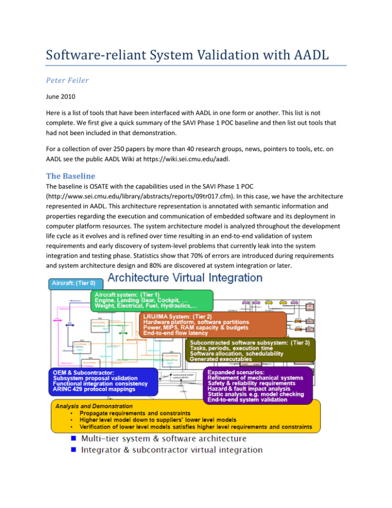
Software-reliant System Validation with AADL Peter Feiler June 2010 Here is a list of tools that have been interfaced with AADL in one form or another. This list is not complete. We first give a quick summary of the SAVI Phase 1 POC baseline and then list out tools that had not been included in that demonstration. For a collection of over 250 papers by more than 40 research groups, news, pointers to tools, etc. on AADL see the public AADL Wiki at https://wiki.sei.cmu.edu/aadl. The Baseline The baseline is OSATE with the capabilities used in the SAVI Phase 1 POC (http://www.sei.cmu.edu/library/abstracts/reports/09tr017.cfm). In this case, we have the architecture represented in AADL. This architecture representation is annotated with semantic information and properties regarding the execution and communication of embedded software and its deployment in computer platform resources. The system architecture model is analyzed throughout the development life cycle as it evolves and is refined over time resulting in an end-to-end validation of system requirements and early discovery of system-level problems that currently leak into the system integration and testing phase. Statistics show that 70% of errors are introduced during requirements and system architecture design and 80% are discovered at system integration or later. Some analysis tools operate directly on the AADL representation, in other cases the information is exported in an interchange format. For example, resource budgets are transformed into tabular form in CSV file for import into Excel for analysis. For other analysis tools the information is translated into a tool-specific representation such as timing model for scheduling analysis. In other words, information from the AADL model is translated into an analysis model representation, either tool specific or in a standardized form. OSATE also maintains detailed tool-specific models of individual components in the repository. These models are not linked models in that they replicate information already present in the AADL model. Instead these are detailed models represent the internals of components that are abstractly captured as an individual AADL component annotated with properties. The detailed model must be checked for compliance with the abstraction. An example is the Ada source code of the subsystem modeled by Keith. The code complements the architecture model, refining the functional behavior of a component. An abstraction of it is reflected in the AADL-level component via properties and it is associated with the AADL model via a property. ASSERT/TASTE from ESA This is the tool chain presented by Eric Conquet at the Toulouse meeting (see also his presentation at the Feb 2010 AADL User day https://wiki.sei.cmu.edu/aadl/images/a/a5/10_02_09-AADL_User_DayTASTE-ESA.pdf). Jerome Hugues presented the work from the code generation perspective out of Ocarina (https://wiki.sei.cmu.edu/aadl/images/f/f1/10_02_09-AADL_User_Day-Ocarina.pdf). The tool chain is built around AADL and is available. Key characteristics of this tool chain are the ability to complement architecture models in AADL with complementary models in other notations. They have included three examples: • ASN.1 as a standardized data modeling representation. Data models of the system are expressed in ASN.1 and kept in the repository. They are associated with the architecture model and aspects relevant to the architecture are mapped into AADL architecture abstraction. For example, the data component type is used to represent an abstraction of the data types in the data model. Only architecturally relevant information from the data model is recorded on the architectural side. This is kept to a minimum and must be consistent with the data in the data model. This is an example of option 3 (BOC in the form of a standard data modeling representation). Based on this experience, the Data Model Annex has now been developed to provide a standardized way of providing an abstraction of data models in the architecture model part of the model repository. This provides a semantically consistent and standardized linkage of either BOC models or analysis specific models in the repository to the architecture model –acting as the primary reference model. They together are the source to which tools interface via the model bus, either to work on (subsets) of the models directly, or to work on analysis-specific models that have been generated from the annotated reference model. The data model combined with the AADL model is input to the Ocarina code generation tool • • suite to produce an architecture-specific runtime executive, data types in the source language and methods for marshalling data for transmission between components. SCADE is an industry (Esterel Technologies) modeling notation to formally capture system behavior with a supporting tool suite. SCADE specifications for individual components are kept in the model repository in its native representation and associated with particular architectural component specifications in AADL. SCADE is combined with AADL (as well as ASN.1 and Simulink). This falls under Option 2. More on Behavior representation later. Simulink supports continuous time & discretized time control behavior specifications. It also offers behavior specification through StateFlow. When combined the two are used in modeling hybrid control systems. In this context the control behavior specification in Simulink is kept in the model repository as a detailed model of control components. Ocarina combines these detailed specifications with the AADL model to generate an implementation of an application specific runtime system and the application code from these validated models. Simulink & AADL with Emmeskay and Ocarina This work was presented by Emmeskay & Hugues at the June 2009 and the Nov 2009 User Days (https://wiki.sei.cmu.edu/aadl/images/6/69/SimulinkToAADL-112009.pdf) and described in two papers (https://wiki.sei.cmu.edu/aadl/images/d/d3/GVSETS09_Emmeskay_TP_GenEmbeddedSoftware.pdf & http://www.erts2010.org/Site/0ANDGY78/Fichier/PAPIERS%20ERTS%202010/ERTS2010_0050_final.pdf [ERTS2010]). Developers who live and breathe Simulink use this tool to represent architectural aspects of their systems through the subsystem blocks of Simulink together with the detailed design of the control system in terms of control blocks. Emmeskay has a tool for importing such Simulink models into a model repository. Instead of just storing the full model the tool separates the architecture portion from the detailed design model portion. The result is a model of the architecture in AADL with the detailed design models in Simulink stored in the repository and associated with the architecture components representing the control components. In order to achieve the full mapping into AADL they have utilized the Simulink capability to refine subsystem blocks into user-defined block with additional information to represent AADL concepts such as threads and processes. In other words, the Simulink modeling tool has been tailored to act as an AADL model front-end. Emmeskay is able to reconstitute an Simulink model that integrated the individual Simulink component models for Simulation runs in the Simulink tool suite. It can also do so for models that originate as AADL models and are then annotated with detailed design models in Simulink. The same combination of AADL model and Simulink detailed design component models are integrated by the Ocarina tool suite into an implementation with code generated for an architecture-specific runtime system and for the control components (utilizing the Mathworks Realtime Workbench to generate the application code). This scenario shows how we can reduce the overlap between the architecture model and the application tool-specific model by separating the architecture information and partitioning the application model into consistently integrated detailed models with minimal overlap with the architecture model within the repository. Rapid Prototyping through Simulation & Code Generation We emphasize analysis of AADL models. We do not intend to limit this to static analysis. In some cases we may not yet understand what the static analysis should be. In other cases we may want to validate the analysis and its results through simulation and actual system execution. AADL Simulators There exist three simulators for the execution of AADL models. • • • ADeS (https://wiki.sei.cmu.edu/aadl/index.php/ADeS): It is a set of plug-ins to OSATE and support the simulated execution of AADL task models. Furness toolset (http://www.furnesstoolset.com/): This toolset lives on top of OSATE. It includes the integration of a scheduling analyzer (VERSA) based on a process algebra (ACSR). It also includes a simulator for the execution of AADL tasks based on the same underlying representation as VERSA/ACSR. This assures consistency between the scheduling analysis results and the executed simulation. Multi-agent model animation for AADL models by ElliDiss https://wiki.sei.cmu.edu/aadl/images/d/d9/20100204_AADLUserDaEllidiss-Update.pdf ) Airbus has taken such a simulation approach and demonstrated co-simulation of hardware and software through a combination of AADL model and other model representations (http://www.dateconference.com/archive/conference/proceedings/PAPERS/2009/DATE09/PDFFILES/04.3_1.PDF ) Prototyped Implementations with Ocarina Ocarina automatically generates runtime systems that reflect the specifics of an embedded software system runtime architecture as specified in an AADL model. Ocarina can generate for single processor platforms, for distributed platforms generating a distributed runtime system as appropriate utilizing the PolyOrb kernel (which was validated via its Petri net-based specification), and for partitioned architectures such as ARINC653 utilizing a Partitioned Operating system Kernel (POK). For more Ocarina, PolyOrb & POK see http://penelope.enst.fr/aadl/ . Ocarina has been used to generate executable versions of systems described in AADL without application code. This allows you to test the task and communication architecture of your application well before developing the code for individual application components. The generator produces application code stubs that use up processor cycles according to the AADL specification. Julien Delange (ENST/Telecom ParisTech now at ESA) has even prototyped generation of communication code for an end-to-end flow, where the source gets a time stamp, this time stamp is communicated as data along the flow and the flow sink compares the received timestamp against its local time. This provides a simple way of generating an end-to-end latency trace for a particular runtime architecture. This can be quite useful for gaining early insight into the execution behavior of an actual implementation of an ARINC653 runtime system, for example. Ocarina & ARINC653 Julien Delange has done his Ph.D. work on the topic of safety & security in the context of partitioned architectures. He has been the primary author of the ARINC653 Annex for AADL, which just passed ballot and incorporates Update 3 changes to the ARINC653 standard. Ocarina support generation of runtime system implementations of ARINC653. It utilizes POK (http://pok.gunnm.org/) and it generates a complete implementation including ARINC653 configuration files in the ARONC653 XML standard representation. A recent paper talks about validation, simulation, and implementation of ARINC 653 (http://portal.acm.org/citation.cfm?id=1653616.1647435 ). AADL, Reliability, and Fault Impact The AADL standard suite includes an Error Model Annex standard that was published in June 2006. The purpose of the Error Model Annex is to extend the core AADL Meta model with a semantically consistent set of concepts to support modeling of fault, error, and hazard behavior in systems, such that analysis models such as stochastic reliability models, fault tree models, and fault impact models (e.g., for FMEA) can be automatically generated from annotated architecture reference models in the model repository. The Error Model Annex has been designed to reflect fault and error behavior at both the system and at the embedded software level. Guidance on the use of the Error Model Annex for dependability modeling was developed by Rugina & Feiler (http://www.sei.cmu.edu/library/abstracts/reports/07tn043.cfm). Several groups prototyped an integration of dependability related analysis capabilities (see below) and based on their experience a revision of the AADL Error Model Annex has just been started to improve its expressive power and its semantics. The Error Model Annex has no specific knowledge that the architecture language it is associated with is AADL – it just has a generic mechanism to identify elements in a component-based language, thus, could be applied to SysML models as well. • Aerospace Corp. toolset (Hecht – see https://wiki.sei.cmu.edu/aadl/images/0/06/HechtFaultModelingMay2010.pdf and https://wiki.sei.cmu.edu/aadl/images/7/78/Vogl_Hecht_Lam_Aerotech_09.pdf ). This toolset is integrated with OSATE generates GSPN from AADL models annotated with error behavior via the Error Model annex. This GSPN representation for a specific tool could in the future be replaced by the ISO standard Petri net markup language (XML). From this GSPN a translator generates Stochastic Activity Network model in the Mobius toolset format. Mobius is a modelbased environment for validating reliability and availability of systems (http://www.mobius.illinois.edu/ ). It is used to calculate reliability in terms of MTBF and other reliability measures. A second translator generates an FMEA representation for FMEA analysis. The SEI is in the process of integrating this toolset into a configuration that extends the SAVI Phase 1 POC to demonstrate end-to-end reliability validation in a SAVI Phase 2 scenario. • • • • Fault Tree generation by Honeywell (see paper http://portal.acm.org/citation.cfm?id=1334422 and presentation http://www.cs.kent.ac.uk/events/conf/2007/wads/Slides/joshi.pdf). Originally, Vestal had extended MetaH with an error model and illustrated the generation and analysis of fault trees. Such a translator has been repeated for AADL and the Error Model Annex – unfortunately not in a publically accessible tool. The COMPASS project led by Thomas Noll at the U. Aachen (http://compass.informatik.rwthaachen.de/) has developed a modeling notation (SLIM) and tools for co-design of dependable system and software that is an extension of AADL and the Error Model Annex. They have put together a tool chain for checking different aspects of system architectures http://www.informatik.uni-freiburg.de/~wimmer/pub/bozzano-et-al-cav-2010-final.pdf). Their tool chain will be available publically this summer. For more see COMPASS section below. WW Technology and Lutz Wrage have both developed a prototype tool on top of OSATE for fault propagation and impact analysis, WW Technology emphasizing a graphical user interface, and Wrage emphasizing propagation support across both embedded software and hardware. WW Technology currently has SBIR Phase 2 funding to extend their tool capability. AltaRica is a modeling notation for modeling functional and dys-functional behavior with both non-commercial and commercial tool support. For example, Dassault has a toolbench and uses AltaRica on in-house projects. Under ASSERT an effort has been started to develop a transformation between AADL annotated with the Error Model and AltaRica. This effort has recently been resumed. COMPASS The COMPASS platform is an integrated tool chain, based on state-of-the-art tools and symbolic model checking techniques, for verification and validation of AADL models (http://www.informatik.unifreiburg.de/~wimmer/pub/bozzano-et-al-cav-2010-final.pdf ). It builds upon the NuSMV symbolic model checker, the MRMC probabilistic model checker, the Sigref bisimulation minimization tool, and the RAT requirements analysis tool. It refers to two inputs, namely the SLIM model (our extended variant of AADL) and property patterns. The latter describe properties, expressed in the user-friendly patterns by Grunske and Dwyer, which are converted to respectively CSL, LTL and CTL formulae. These inputs are processed into the lower-level formalisms of NuSMV and MRMC. A set of visualizers transforms the output (like counterexample traces and fault trees) back to the user. Feature-wise, the toolset supports the following analyses. • • Requirements Validation, implemented by RAT, focuses on assessing the quality of a set of requirements with respect to the user expectations, before a model of the actual system is built. It is possible to check that a set of properties is logically consistent, and that it is strict enough but not too strict, by checking for compatibility with a set of possibilities, and for logical consequence of a set of assertions. Functional Verification comprises random and user-guided simulation, deadlock detection, and verification of functional properties via model checking. The result can be a statement that a property holds, or a counterexample or witness trace, in case the property is refuted or for • • • • simulation. This analysis is based on NuSMV, which supports BDD-based, SAT-based, and (for hybrid systems) SMT-based model checking. Safety Analysis comprises traditional techniques for hazard analysis, such as (Dynamic) Fault Tree Analysis (FTA) and Failure Mode and Effects Analysis (FMEA), that are used to assess system behavior in presence of faults. FTA constructs all possible chains of basic faults, represented as a tree, that may be responsible for an undesired behavior. FMEA is similar, but starts from a set of faults and analyzes the impact on a set of properties. Diagnosability Analysis checks whether a system is diagnosable with respect to a user-specified property, that is, whether an ideal diagnoser has enough observations to identify the set of causes of a specific faulty behavior. Fault Detection, Isolation and Recovery (FDIR) focus on, respectively, verifying whether a given fault can be properly detected, isolated and recovered. Performance Evaluation computes, using a probabilistic property, system performance under degraded operations. It furthermore includes the evaluation of fault trees by computing the probability of the top event. These analyses are based on MRMC. For more details see the project’s website (http://compass.informatik.rwth-aachen.de/). Behavior Modeling, Validation & Verification Behavior modeling and validation has been demonstrated in the context of AADL in a number of ways. It shows a migration of solutions between the three Model Bus options discussed by Lempia (Option 1: AADL & Behavior Annex, Option 2: analysis tool specific models in repository; Option 3: BOC analysis model interchange format via Lustre/FIACRE). • It has been shown how AADL models can be completed with behavioral models in tool-specific representations for analysis and generation. One example is the combination of AADL and SCADE through Ocarina mentioned earlier. Other possibilities are to associate Mathworks StateFlow models as detailed behavior models for components. Miller et.al. (Rockwell Collins) has demonstrated the ability to translate StateFlow representations into more formal notations such as NuSMV using Lustre as common interchange representation. • • The French COTRE study resulted in a proposal for a standardized interchange format for formal verification and model checking notations and tools called FIACRE (http://hal.inria.fr/docs/00/26/24/42/PDF/Berthomieu-Bodeveix-Farail-et-al-08.pdf) – a close cousin to Lustre. The same group also proposed a Behavior Annex for AADL that has just passed ballot – an Option 1 extension to the AADL Meta model as model repository representation. A front-end for the Behavior Annex has been implemented by ElliDiss and Telecom ParisTech. Filali et.al. have implemented a translator from AADL & Behavior Annex to FIACRE as well as a translation from FIACRE to TINA – a TIme Petri Net Analyser(http://homepages.laas.fr/bernard/tina/ ). BIP and AADL by Verimag. Behavior Interaction Priority (BIP) is a formal notation for incremental composition of components ensuring correctness by construction. Verimag has built a translator to map AADL models into BIP specifications for verification (http://wwwverimag.imag.fr/BIP,196.html?artpage=3 ). See also a SPCIES tool chain with BIP (from https://lirias.kuleuven.be/bitstream/123456789/252297/1/SPICES-FDL-K.U.Leuven+v3.pdf ) • • BLESS by Brian Larson (Member of the SAE AADL committee). The Behavioral Language for Embedded Systems with Software (BLESS) was created to be an annex sublanguage of the Architecture Analysis and Design Language (AADL) (https://wiki.sei.cmu.edu/aadl/images/b/b5/BLESS_Annex_v0.12-May2010.pdf ). AADL architectures augmented with BLESS behaviors allows safety-critical systems to be proved correct. Brian has a demonstration of the BLESS proof tool prototype that emits a formal proof of thread behavior when proof-checking passes (https://wiki.sei.cmu.edu/aadl/images/3/31/LarsonBlessAADLMay2010.pdf) . Other experimental interfacing with behavioral model checkers includes o Jose Meseguer interfacing Maude to AADL (http://www.stsc.hill.af.mil/crosstalk/2009/09/0909Sha.html and paper https://agora.cs.illinois.edu/download/attachments/22843494/FormalizedArchitecture. pdf ). See also U Leicester (http://www.cs.le.ac.uk/people/aboronat/tools/moment2aadl/ ). Evaluation of Timing Properties A number of scheduling analyzers have been interfaced to AADL including • • • Dio DeNiz’s Binpacker for allocation of tasks to processors, memory taking into account network resrouces using a binpacking techniques (part of OSATE) VERSA/ACSR for scheduling analysis based on a process algebra (see above) Cheddar for scheduling analysis based on Timed Automata (https://wiki.sei.cmu.edu/aadl/index.php/Cheddar ) and (http://beru.univbrest.fr/~singhoff/cheddar ). Other experimentation with mapping AADL into time-based analysis models include • • • Lundquist on AADL mapped into the Timed Abstract State Machines (TASM) language, which then is translated into UPPAAL for analysis (http://www.springerlink.com/content/fg7547j3qq5274tx/ ) Oleg Sokolsky on an automated mapping between UPPAAL Timed Automata and AADL with the Behavior Annex (https://wiki.sei.cmu.edu/aadl/images/b/b4/20091109-TA2BA-UPenn.pdf ) Dio deNiz interfacing AADL to Alloy for exploring concurrency issues then reimplemented in a OSATE analysis plug-in directly operating on the AADL model and extended with the ability to take into account time. This plug-in was used in the dual Flight Guidance add-on to the SAVI Phase 1 POC demo. We recently started interacting with a company called Edgewater (www.edgewater.ca) that has an interesting toolset for real-time system modeling with a formally defined underlying FSM-based behavior and associated time model (see presentation at SAE Aerotech https://wiki.sei.cmu.edu/aadl/images/f/f3/RTEdge_Aerotech.Nov2009.pdf ). They support verification of the behavior description and flow-based scheduling analysis based on a refined RMA algorithm. Their concepts can be mapped well into AADL and they expressed in doing so and exploring the idea of an AADL micro-kernel based on RTEdge. They started participating in the AADL committee. They are interested in exposing their work to SAVI. Other Opportunities There are several other opportunities of leveraging external analysis integration efforts to better understand and illustrate the model repository and model bus strategy for SAVI. • REAL as constraint language to express requirements-like constraints on the model. REAL is a close cousin to OCL. An implementation for REAL was done by Telecom ParisTech and presented at the Feb 2010 AADL User day (https://wiki.sei.cmu.edu/aadl/images/2/25/20100204_AADLUserDay-delangerealConstraintLanguage.pdf ). They are thinking about proposing it as an Annex standard to AADL. • • • Mapping formal requirements onto AADL via FAUST (http://www.cetic.be/faust.php3 ) based on Goal-Oriented Requirements Engineering (GORE) by Lamsweerde. See paper at http://ieeexplore.ieee.org/stamp/stamp.jsp?tp=&arnumber=5090547. ASIIST: Application Specific I/O Integration Support Tool for Real-Time Bus Architecture Designs by Sha et.el. at UIUC. See website https://agora.cs.illinois.edu/display/realTimeSystems/ASIIST and paper http://www.computer.org/portal/web/csdl/doi/10.1109/ICECCS.2009.31. See also “Rapid Early-Phase Virtual Integration” https://netfiles.uiuc.edu/rpelliz2/www/index_files/papers/early.pdf or “Resilient Mixedcritiality Systems” http://www.stsc.hill.af.mil/crosstalk/2009/09/0909Sha.html in Crosstalk. CAT: Multi-level power consumption analysis tool by Lab-STICC (http://sourceforge.net/apps/trac/lab-sticc/ ). See papers “FDL Senn 2008” and “MODELS Senn 2008” at https://wiki.sei.cmu.edu/aadl/index.php/2008_Publications ).

