Document 12969740
advertisement
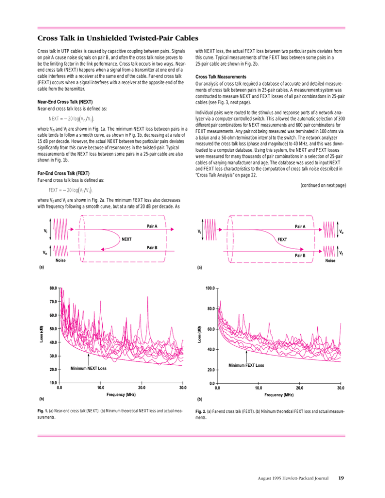
Cross talk in UTP cables is caused by capacitive coupling between pairs. Signals on pair A cause noise signals on pair B, and often the cross talk noise proves to be the limiting factor in the link performance. Cross talk occurs in two ways. Nearend cross talk (NEXT) happens when a signal from a transmitter at one end of a cable interferes with a receiver at the same end of the cable. Far-end cross talk (FEXT) occurs when a signal interferes with a receiver at the opposite end of the cable from the transmitter. Near-End Cross Talk (NEXT) Near-end cross talk loss is defined as: NEXT = 20 logV nV i, where Vn and Vi are shown in Fig. 1a. The minimum NEXT loss between pairs in a cable tends to follow a smooth curve, as shown in Fig. 1b, decreasing at a rate of 15 dB per decade. However, the actual NEXT between two particular pairs deviates significantly from this curve because of resonances in the twisted-pair. Typical measurements of the NEXT loss between some pairs in a 25-pair cable are also shown in Fig. 1b. Far-End Cross Talk (FEXT) Far-end cross talk loss is defined as: with NEXT loss, the actual FEXT loss between two particular pairs deviates from this curve. Typical measurements of the FEXT loss between some pairs in a 25-pair cable are shown in Fig. 2b. Cross Talk Measurements Our analysis of cross talk required a database of accurate and detailed measurements of cross talk between pairs in 25-pair cables. A measurement system was constructed to measure NEXT and FEXT losses of all pair combinations in 25-pair cables (see Fig. 3, next page). Individual pairs were routed to the stimulus and response ports of a network analyzer via a computer-controlled switch. This allowed the automatic selection of 300 different pair combinations for NEXT measurements and 600 pair combinations for FEXT measurements. Any pair not being measured was terminated in 100 ohms via a balun and a 50-ohm termination internal to the switch. The network analyzer measured the cross talk loss (phase and magnitude) to 40 MHz, and this was downloaded to a computer database. Using this system, the NEXT and FEXT losses were measured for many thousands of pair combinations in a selection of 25-pair cables of varying manufacturer and age. The database was used to input NEXT and FEXT loss characteristics to the computation of cross talk noise described in “Cross Talk Analysis” on page 22. (continued on next page) FEXT = 20 logV fV i, where Vf and Vi are shown in Fig. 2a. The minimum FEXT loss also decreases with frequency following a smooth curve, but at a rate of 20 dB per decade. As Pair A Pair A Vi Vo Vi NEXT FEXT Pair B Vn Vf Pair B Noise Noise (a) (a) 80.0 100.0 70.0 80.0 Loss (dB) Loss (dB) 60.0 50.0 40.0 60.0 40.0 30.0 Minimum FEXT Loss Minimum NEXT Loss 20.0 20.0 10.0 0.0 0.0 10.0 20.0 30.0 0.0 Frequency (MHz) (b) Fig. 1. (a) Near-end cross talk (NEXT). (b) Minimum theoretical NEXT loss and actual measurements. 10.0 20.0 30.0 Frequency (MHz) (b) Fig. 2. (a) Far-end cross talk (FEXT). (b) Minimum theoretical FEXT loss and actual measurements. (continued from page 19) Controller Network Analyzer Controller Network Analyzer 251 Switch 251 Switch 100-Ohm Termination 252 Switch 25-Pair Cable 25-Pair Cable For FEXT Loss For NEXT Loss (continued from page 18) Given these constraints, the design goals for the PHY wereĆ met by developing a physical medium dependent (PMD) subĆ layer for each media type (UTP, STP, and multimode optical fiber) and a physical medium independent (PMI) sublayer that contains all the functions common to all media types. These two sublayers together form the demand priority PHY. In the remainder of this article we will discuss the design choices made for each of the three demand priority PMDs. The FourĆPair UTP PMD The first PMD to be developed was to support UTP cabling, since this addresses the large 10BaseĆT upgrade market. 10BaseĆT uses fullĆduplex signaling at 10 Mbit/s on UTP cabling.2 One twisted pair is used to transmit and one to receive data. The dc content of the signal is minimized by Manchester coding the data before transmission on the twistedĆpair channel. Manchester coding is a very simple form of block coding: This is a 1B/2B block code, and results in a 100% bandwidth expansion. Manchester coding is spectrally inefficient relative to other block codes, but does provide a guaranteed transiĆ tion for every two symbols, has very low dc content, and is very simple to implement. The transmission rate in 10BaseĆT is 20 megabaud, giving a data rate of 10 Mbits/s (1 baud is one symbol per second). This means that the transmitted signal can be lowĆpass filĆ tered with a cutoff frequency somewhat less than 20 MHz. This helps minimize radiated emissions above 30 MHz, the lower bound of stringent EMC regulations. From 10BaseĆT to 100VGĆAnyLAN The progression from 10BaseĆT to 100VGĆAnyLAN was made in three simple steps. First, it was recognized that since fullĆduplex transmission was not absolutely necessary in a hubĆbased network, both twisted pairs used for 10BaseĆT could be used simultaneously 20 August 1995 HewlettĆPackard Journal Fig. 3. Measurement system for NEXT and FEXT loss. for transmission in one direction or reception in the other. This immediately doubles the bit rate achieved on existing 10BaseĆT networks. Second, the spectrally inefficient Manchester code was replaced with a more efficient 5B/6B block code (5 bits of data are coded to 6 transmitted binary symbols). This reduced the bandĆ width overhead from 100% with Manchester coding to 20%. As a result, the data rate on each pair could be increased to 25 Mbits/s (that is, a symbol rate of 30 megabaud after 5B/6B coding) while the main lobe of the data spectrum remained below 30 MHz, the lower limit of EMC regulations. As with 10BaseĆT, lowĆpass filtering with a cutoff below 30 MHz can then be applied to minimize the risk of excessive radiated emissions. The 5B/6B code chosen also has very low dc conĆ tent, which avoids distortion from the coupling transformers. See the article on page 27 for more details. Third, the UTP PHY takes advantage of the two unused pairs available in every fourĆpair cable. Surveys of customer cable plants revealed that a large proportion of these customers adĆ hered to structured cabling recommendations3 when installing cable, and connected fourĆpair cable to each wall outlet. Two of these four pairs currently lie unused. By transmitting 5B/6B coded data at 30 megabaud on all four pairs, it is possible to provide a total signaling rate of 120 megabaud (100 Mbits/s) over UTP cable. Quartet Signaling The fourĆpair transmission scheme, called quartet signalĆ ing, uses binary transmission, that is, only two voltage levels are used as symbols. Other approaches to the UTP PMD were examined. One was multilevel (mĆary) signalĆ ing (see Multilevel Signaling" on page 21). In a multilevel scheme, n data bits are mapped to one of m = 2n symbols, and each symbol is a unique voltage level. For example, in a quaternary scheme, two data bits may be mapped to one of four voltage levels. In this way the number of symbols transmitted, and hence the transmission rate required, is reduced by a factor of n. However, for a fixed power supĆ ply voltage, the voltage separation between symbols is reduced by a factor of 1/(m1) from the binary case. The binary quartet signaling scheme maximizes the voltage separation between symbols, which provides greater imĆ munity to noise at the receiver.
