Temperature Monitoring System Akshay Chandrachood , Pritee Kulkarni
advertisement
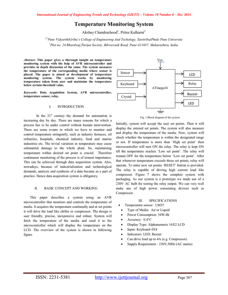
International Journal of Engineering Trends and Technology (IJETT) – Volume 18 Number 8 – Dec 2014 Temperature Monitoring System Akshay Chandrachood1, Pritee Kulkarni2 1,2 Pune VidyarthiGriha’s College of Engineering And Techology, SavitribaiPhule Pune University 1 Plot no. 24 Bhardwaj,Parijat Society, Bibwewadi Road, Pune-411037, Maharashtra, India. Abstract- This paper gives a thorough insight on temperature monitoring system with the help of AVR microcontroller and provides in depth discussion of the same. The system measures the temperature of the corresponding media where sensor is placed. The paper is aimed at development of temperature monitoring system. The system works by monitoring temperature taken from user and maintains the temperature below certain threshold value. Vcc Sensor ATmega16 Buzzer Crystal LED INTRODUCTION In the 21st century the demand for automation is increasing day by day. There are many reasons for which a process has to be under control without human intervention. There are some events in which we have to monitor and control temperature stringently, such as industry furnaces, oil refineries, hospitals, chemical industry, food and marine industries etc. The trivial variation in temperature may cause substantial damage to the whole plant. So, maintaining temperature within desired set point is crucial. Therefore continuous monitoring of the process is of utmost importance. This can be achieved through data acquisition system. Also, nowadays, because of industrialization and technological demands, analysis and synthesis of a data became as a part of practice. Hence data acquisition system is obligatory. II. Relay Keyboard Keywords- Data Acquisition System, AVR microcontroller, temperature sensor, relay. I. LCD BASIC CONCEPT AND WORKING This paper describes a system using an AVR microcontroller that monitors and controls the temperature of media. It acquires the temperature continually and at set points it will drive the load like chiller or compressor. The design is user friendly, precise, inexpensive and robust. System will fetch the temperature of the media and send it to the microcontroller which will display the temperature on the LCD. The overview of the system is shown in following figure. ISSN: 2231-5381 Fig. 1 Block diagram of the system Initially, system will accept the user set points. Then it will display the entered set points. The system will also measure and display the temperature of the media. Now, system will check whether the temperature is within the designated range or not. If temperature is more than ‘High set point’ then microcontroller will turn ON the relay. The relay is kept ON till the temperature reaches ‘Low set point’. The relay will remain OFF for the temperature below ‘Low set point’. After that whenever temperature exceeds these set points, relay will operate. To enter new set points ‘RESET’ button is provided. The relay is capable of driving high current load like compressor. Figure 7 shows the complete system with packaging. As our system is a prototype we made use of a 230V AC bulb for testing the relay output. We can very well make use of high power consuming devices such as Compressor. III. SPECIFICATIONS Temperature sensor: LM35 Type of Media: Air or Liquid Power Consumption: 54W-Hr Accuracy: 0.4°C Display Type: Alphanumeric 16X2 LCD Input: Keyboard 4X4 Indicators: LED, Buzzer Can drive load up to 4A (e.g. Compressor) Supply Requirement : 230V,50Hz (AC mains) http://www.ijettjournal.org Page 367 International Journal of Engineering Trends and Technology (IJETT) – Volume 18 Number 8 – Dec 2014 IV. CIRCUIT DESCRIPTION The temperature sensor LM-35 can be calibrated directly into degree Celsius. Also, it will eliminate the need of signal conditioning. Pin +Vs is connected to +5V (supply), output pin is connected to pin PA1 of controller and ground of LM-35 is connected to the ground pin of ATmega16A. The data sent from sensor is analog in nature. So, we have to convert it into digital form. Using internal ADC of ATmega16A the digital data is obtained. The reference voltage of 2.56V is provided on chip. The data is displayed on 16X2 alphanumeric LCD. The 4X4 keypad consists of numbers from 0 to 9 and buttons such as ‘Set High’, ‘Set Low’ and ‘ENTER’ etc. User will give the set points from keypad. After set point is reached, 4N25 optocoupler IC will make the relay ON or OFF. Across the relay LED and buzzer are connected for visual and audio indication respectively. Reset pin is connected to +5V through 10K resistor. Pin no.11 and 31 are connected to ground. Pin no.30 is AVcc. AVcc should be connected to Vcc through low pass filter which is supply voltage for PORT A and ADC. Pin no.32 is AREF that is analog reference pin for ADC. ATmega16A has capability to achieve throughput of executing 1MIPS allowing the system designer to optimize power consumption versus processing speed. A. Software Part We are making use of embedded C instead of assembly language which provides much better flexibility. The flowcharts are shown in figures 2 and 3 respectively. Fig. 2 Flowchart for the development of code Fig. 3 flowchart for the development of the code ISSN: 2231-5381 http://www.ijettjournal.org Page 368 International Journal of Engineering Trends and Technology (IJETT) – Volume 18 Number 8 – Dec 2014 B. Simulation Results Before hardware implementation, circuit was tested on ‘Proteus version 7’. It gives clear idea of actual hardware. The simulated circuit is shown in figure 4 and 5. Fig. 7 Hardware implementation with packaging Fig. 4 Simulation results when LM35 has 250C Fig. 8 Entering and displaying set points Fig. 5 Simulation of circuit C. Hardware Results V. ADVANTAGES AND DISADVANTAGES A. Advantages: It measures the temperature with 0.40C accuracy. It has audible alarm (Buzzer) as well as visible alarm (LED) facility. Instrument requires only AC mains (230V, 50Hz, Single phase) connection. System can drive the high current rating applications such as compressors. (Max output current 4A) Light weight. Low power consumption. B. Disadvantages No portability due to the requirement of AC mains supply. No USB interface and provision of SD card storage. Fig. 6 Hardware Testing ISSN: 2231-5381 VI. APPLICATIONS Such a system has prime applications in industries where precise monitoring of any media is required. Such industries include: http://www.ijettjournal.org Page 369 International Journal of Engineering Trends and Technology (IJETT) – Volume 18 Number 8 – Dec 2014 In oil and gas industry, monitoring of temperature and pressure is important factor from safety point of view. In chemical industries some fuels are heated using water bath. Here, the temperature of the water bath as well as temperature of fuel is very important. In that case data acquisition system plays an important role by maintaining the required temperature of water bath and fuel. In the blast furnace, fractional distillation process is carried out to separate different elements such as petrol, diesel, natural gas etc. at different temperatures. It is required to measure temperature and open the corresponding valves to separate the constituents. This can be implemented through data acquisition system. Food industry and biomedical industry are some of the complimentary applications of this system. ACKNOWLEDGEMENT The completion of any project brings with it a sense of satisfaction, but it is never complete without thanking those people who made it possible and whose constant support has crowned our efforts with success. It is difficult to express all that we feel, as words are such that they do not do adequate justice for the feelings one has, but silent feeling cannot be expressed if they are not given in the form of words. We take this opportunity to express our heartfelt gratitude towards the teaching as well as non-teaching staff of our department. Our teachers helped us in materializing our ideas. Their help and support at each stage helped us in completing the project successfully. We have great pleasure in presenting the paper on ‘Temperature Monitoring System’ and we are extremely happy to acknowledge and express our sincere gratitude to friends and well-wishers for their help and cooperation and solutions to the problems during the course of the project. REFERENCES VII. FUTURE SCOPE There always remains an infinite scope of improvement to an instrument design, though time and financial constraints impose a limit on the development. Following are the few enhancements that may add further value to the product: We can use external EEPROM to store the data Currently the temperature displayed on LCD is not with respect to date and time. We can interface an RTC (Real Time Clock) to display date and time One can also use more precise sensor for wider range of applications. Nowadays, the sophisticated way for data storage is to have the facility of external SD card. This will make the system more versatile. Use of smart phones, tablet or computer to receive alerts and remotely monitor temperature and humidity levels that affect our home, business or vacation home or rentals. [1] http://ieeexplore.ieee.org/xpl/ Article on advanced fluid temperature sensor [2] Electronics for you (magazine-Feb 2014) [3] Power Electronics by Khanchandani [4] The AVR microcontroller and embedded system using assembly and C by Mahammad Ali Mazidi.(2011) [5] http://www.ti.com [6] Introduction to measurements and instrumentation by Arun K. G VIII. CONCLUSION This system is useful in various fields where temperature monitoring is required. Because of the implementation of temperature monitoring system we can keep multiple processes under control. The system is capable of driving high current loads. The system has achieved an accuracy of 0.4oC. Considering the merits and demerits, the ATmega16A based circuitry used for this project is versatile. The use of 4N25 isolated analog and digital circuit. It also gives added sturdiness to the system. The system has ample scope of improvements which were discussed in section VII. Thus this project has successfully met our requirements. ISSN: 2231-5381 http://www.ijettjournal.org Page 370
