Car Park Charger Using Witricity Adarsh Srinivas , Deepak Gadodia
advertisement
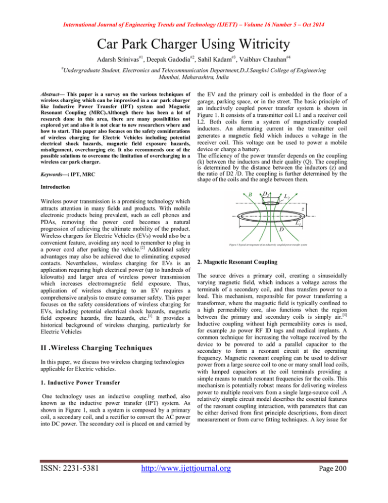
International Journal of Engineering Trends and Technology (IJETT) – Volume 16 Number 5 – Oct 2014 Car Park Charger Using Witricity Adarsh Srinivas#1, Deepak Gadodia#2, Sahil Kadam#3, Vaibhav Chauhan#4 # Undergraduate Student, Electronics and Telecommunication Department,D.J.Sanghvi College of Engineering Mumbai, Maharashtra, India Abstract— This paper is a survey on the various techniques of wireless charging which can be improvised in a car park charger like Inductive Power Transfer (IPT) system and Magnetic Resonant Coupling (MRC).Although there has been a lot of research done in this area, there are many possibilities not explored yet and also it is not clear to new researchers where and how to start. This paper also focuses on the safety considerations of wireless charging for Electric Vehicles including potential electrical shock hazards, magnetic field exposure hazards, misalignment, overcharging etc. It also recommends one of the possible solutions to overcome the limitation of overcharging in a wireless car park charger. Keywords—: IPT, MRC the EV and the primary coil is embedded in the floor of a garage, parking space, or in the street. The basic principle of an inductively coupled power transfer system is shown in Figure 1. It consists of a transmitter coil L1 and a receiver coil L2. Both coils form a system of magnetically coupled inductors. An alternating current in the transmitter coil generates a magnetic field which induces a voltage in the receiver coil. This voltage can be used to power a mobile device or charge a battery. The efficiency of the power transfer depends on the coupling (k) between the inductors and their quality (Q). The coupling is determined by the distance between the inductors (z) and the ratio of D2 /D. The coupling is further determined by the shape of the coils and the angle between them. Introduction Wireless power transmission is a promising technology which attracts attention in many fields and products. With mobile electronic products being prevalent, such as cell phones and PDAs, removing the power cord becomes a natural progression of achieving the ultimate mobility of the product. Wireless chargers for Electric Vehicles (EVs) would also be a convenient feature, avoiding any need to remember to plug in a power cord after parking the vehicle.[2] Additional safety advantages may also be achieved due to eliminating exposed contacts. Nevertheless, wireless charging for EVs is an application requiring high electrical power (up to hundreds of kilowatts) and larger area of wireless power transmission which increases electromagnetic field exposure. Thus, application of wireless charging to an EV requires a comprehensive analysis to ensure consumer safety. This paper focuses on the safety considerations of wireless charging for EVs, including potential electrical shock hazards, magnetic field exposure hazards, fire hazards, etc.[1] It provides a historical background of wireless charging, particularly for Electric Vehicles II .Wireless Charging Techniques In this paper, we discuss two wireless charging technologies applicable for Electric vehicles. 1. Inductive Power Transfer One technology uses an inductive coupling method, also known as the inductive power transfer (IPT) system. As shown in Figure 1, such a system is composed by a primary coil, a secondary coil, and a rectifier to convert the AC power into DC power. The secondary coil is placed on and carried by ISSN: 2231-5381 2. Magnetic Resonant Coupling The source drives a primary coil, creating a sinusoidally varying magnetic field, which induces a voltage across the terminals of a secondary coil, and thus transfers power to a load. This mechanism, responsible for power transferring a transformer, where the magnetic field is typically confined to a high permeability core, also functions when the region between the primary and secondary coils is simply air.[4] Inductive coupling without high permeability cores is used, for example ,to power RF ID tags and medical implants. A common technique for increasing the voltage received by the device to be powered to add a parallel capacitor to the secondary to form a resonant circuit at the operating frequency. Magnetic resonant coupling can be used to deliver power from a large source coil to one or many small load coils, with lumped capacitors at the coil terminals providing a simple means to match resonant frequencies for the coils. This mechanism is potentially robust means for delivering wireless power to multiple receivers from a single large-source coil .A relatively simple circuit model describes the essential features of the resonant coupling interaction, with parameters that can be either derived from first principle descriptions, from direct measurement or from curve fitting techniques. A key issue for http://www.ijettjournal.org Page 200 International Journal of Engineering Trends and Technology (IJETT) – Volume 16 Number 5 – Oct 2014 powering of multiple receivers is the coupled mode frequency splitting that occurs when two receivers are in close enough proximity that their magnetic fields are relatively strongly coupled. Control circuitry to track the resonant frequency shifts and to retune the receiving coil capacitances is a potentially viable strategy for addressing this issue. potential fire hazards[1]. These concerns are primarily due to the presence of large power levels, large electromagnetic fields, and operation in potentially hazardous locations (for example, operation in garages with flammable materials). Overcharging: It is the most common and safest type of side-effect but not the only thing that can happen. A battery can quite simply die from being overcharged. An overcharged battery will boil the sulfuric acid and distilled water mix. The casing of the battery can become hot to the touch, and begin to melt or swell. Flammable hydrogen can build up inside the sealed cells of the battery, causing swelling of the casing under pressure and seepage through small vents. Once the hydrogen is introduced to oxygen, it becomes a sitting time bomb. A small electrical spark can ignite the gas and cause the battery to explode, sending plastic and lead shrapnel flying around, in addition to a caustic sulfuric acid spray. III.Block diagram Misalignment: Misalignment of the coils will affect the coupling factor of the system. As such, this will affect the efficiency of the power transfer. However, there are also concerns that misalignment can distort the field in a way that would allow the field to stretch or extend into an adjacent zone [5]. For example, the user cannot be located under the vehicle during charging, but can be located in next to or within the vehicle. If misalignment can cause the field to extend from under the vehicle into the user occupied area next to the vehicle, then a hazardous condition could exist. If this is the case, then misalignment of the coils would become a safety critical issue. Maximum misalignment would need to be controlled for more than just efficiency, and the means to control or mitigate misalignment would become a safety critical system. Field Exposure: Block Diagram of Electromagnetic Induction based Car Park and Charge demonstrating charging technique. IV. Safety considerations and hazards: Wireless charging is accomplished through a coupling of the primary and secondary coils. This involves the generation of electrical and magnetic fields that can be potentially dangerous to the user or others in the vicinity of the vehicle while charging.[3] Although wireless charging systems has many advantages for EV charging, the technology also poses potentially significant safety concerns such as electrical shock due to the high electrical power, high magnetic field exposure to the general public that may exceed standards and FCC regulations, and ISSN: 2231-5381 Electromagnetic field (EMF) exposure is a major concern for wireless charging for EVs. EMF exposure need to be rigorously analysed to be within acceptable levels specified by safety standards, both under normal conditions as well as unusual conditions such as during abnormal operation, presence of a human under the vehicle, potential abuse, etc.[1] For the driver and passengers in the car, the radiation hazard may be less concerned due to the shielding of metal on the chassis of the car. However, there is a possibility that humans or animals may be present underneath the car during charging and therefore be exposed to high levels of electromagnetic radiation. The “radiation zone” of the wireless charger for EV is in the near field of the electromagnetic wave, since both IPT and MRC operate in the near field of the EMF source versus far field which is used for transmitting signals/information for antennas. Exposures in the near field are more difficult to specify because both E and H fields must be studied or measured separately, and because the field patterns are more complicated. Apparently, the most hazardous radiation zone is right between the two coils, and http://www.ijettjournal.org Page 201 International Journal of Engineering Trends and Technology (IJETT) – Volume 16 Number 5 – Oct 2014 secondary hazardous zone is around the coils (not right over the coils but still under the car). These areas are the most hazardous zones but it is noted that they are not directly exposed to humans or animals at all time. Comparing with these areas, another important hazardous zone in need of consideration is near the charger and around the car (not under the car), and it exposes to the general public directly. This area along with the two hazardous areas under the car needs to be considered during the design cycle. V. Solutions The most common way of wearing out of a battery is due to overcharging and the resultant cell damage. To avoid this, we recommend the use of a relay timer circuit which allows us to set the time duration of charging of the battery. The circuit works in manner that it gets automatically disconnected after the specified time interval provided by us. The figure below is the circuit diagram of the relay timer circuit. A temperature signal, or a resettable fuse, can be used to turn off or disconnect the charger when danger signs appear to avoid damaging the battery. This simple additional safety precaution is particularly important for high power batteries where the consequences of failure can be both serious and expensive. The solutions don't just involve the development of chargers, they involve the design and roll out of a network of public and private charging stations with associated user authentication and billing systems, public safety and planning issues, the negotiation of international standards and beefing up the electricity grid to carry the increased load. There are no single answers to these issues. On the one hand, national and international standards organisations attempt to find definitive solutions to these issues, but there are so many competing national standards. On the other hand commercial enterprises attempt to leapfrog the competition by coming up with new and unique innovative solutions to differentiate their offerings. VI. Conclusion and Future scope: Witricity’s technology is a non-radiative mode of energy transfer, relying instead on the magnetic near field. Magnetic fields interact very weakly with biological organisms— people and animals—and are scientifically regarded to be safe. Witricity products are being designed to comply with applicable safety standards and regulations .Hence Witricity is a safe technology. Witricity can transfer power depending on the source and receiver. if they are relatively close to one another, it can exceed 95%.Efficiency is primarily determined by the distance between the power source and capture device, however, the shape may impact the efficiency. The city just has to be covered with Witricity hot spots wherein you can use your electric gadget battery and wire free making it more convenient to carry around and much lighter. With Witricity, there will be no need of charging batteries, or buying new batteries for your electrical gadgets. There will be no need of power cables and batteries. The concept can be further explored on the lines of OLEV wherein the vehicle can be dynamically charged along the road using hotspot pads. VII. References [1] White Paper by Hai Jiang, Paul Brazis Jr., Mahmood Tabaddor and Joseph Bablo, Safety Considerations of Wireless Charger for Electric Vehicles – A Review Paper [2] Dr. Morris Kesler WiTricity Corporation, Highly Resonant Wireless Power Transfer: Safe, Efficient, and over Distance [3] Matthew A. Bloom, GengNiu, Mahesh Krishnamurthy Electric Drives and Energy Conversion Lab, Department of Electrical and Computer Engineering, Illinois Institute of Technology, Design Considerations for Wireless Electric Vehicle Charging [4]A. Kurs, A. Karalis, R.Moffatt, J. D. Joannopoulos, P. Fisher, and M. Soljacic,“Wireless power transfer via strongly coupled magnetic resonances,” Science, vol. 317, pp. 83–86, Jul. 6, 2007. [5] K. Kim, Y. Ryu, E. Park, K. Song and C. Ahn "Analysis of Misalignments in Efficiency of Mid-Range Magnetic Resonance Wireless Power Link", Proc. IEEE AP-S Int. Symp. Dig., Chicago IL, July, 2012. ISSN: 2231-5381 http://www.ijettjournal.org Page 202
