Design and Development of DOA Measurement PCB using FPGA B.Sabitha Rani Ch.Viswandham

International Journal of Engineering Trends and Technology (IJETT) – Volume 14 Number 6 – Aug 2014
Design and Development of DOA Measurement
PCB using FPGA
1
B.Sabitha Rani
2
Ch.Viswandham
3
G.Sreelakshmi
M.Tech Department of ECE D & ESDGM Associate Professor, Department of ECE
Geethanjali College of Bharat Electronics , Geethanjali College of
Engineering And Technology IE Nachara, Hyderabad Engineering and Technology
Telangana, India Telangana, India Telangana, India
Abstract : ESM (Embedded Support Measure) system consists of System antenna, Receiver, Processor and Display subsystem. Receiver is used for measuring radar parameters within few micro seconds (typ. 1µs). These parameters include frequency, pulse width, PRF, amplitude, scan period etc. The receiver measures all these parameters pulse by pulse and provides the data in digital form. DOA measurement is one of the important parameter to be measured. For this purpose Mono-pulse amplitude comparison technique is used. DOA Measurement PCB along with other hardware is required for DOA measurements. This DOA Measurement PCB is to be designed and developed using FPGAs.
Keywords:- ESM system, DOA,FPGA, VHDL
I.
INTRODUCTION
RADAR is an electromagnetic system for the detection and location of reflecting objects such as aircrafts, ships, space crafts, vehicles, people and the natural environment. It operates by radiating energy into space and detecting the echo signal reflected from an object, or target. This energy that is returned to the
RADAR not only indicates the presence of a target, but by comparing the received echo signal that was transmitted, its location can be determined along with
The term RADAR is contraction of the words
“Radio Detection and Ranging”. The name reflects the importance placed.
[4]
II.
RADAR EQUATION
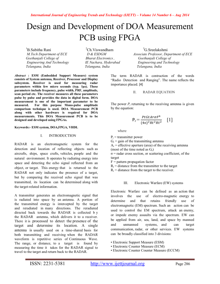
The power P r
returning to the receiving antenna is given by the equation: where
P r
=
( ᴨ )
[1]
P t
= transmitter power
G t
= gain of the transmitting antenna
A r
= effective aperture (area) of the receiving antenna
(most of the time noted as G r
)
σ = radar cross section, or scattering coefficient, of the target
F = pattern propagation factor
R t
= distance from the transmitter to the target
R r
= distance from the target to the receiver.
III.
Electronic Warfare (EW) systems the target-related information.
Electronic Warfare can be defined as an action that
A transmitter generates an electromagnetic signal that is radiated into space by an antenna. A portion of the transmitted energy is intercepted by the target and reradiated in many directions. The reradiated directed back towards the RADAR is collected b y the RADAR antenna, which delivers it to a receiver.
There it is processed to detect the presence of the target and determine its location. A single antenna is usually used on a time-shared basis for both transmitting and receiving when the RADAR waveform is repetitive series of Continuous Wave.
The range, or distance, to a target is found by measuring the time it takes for the RADAR signal to travel to the target and return back to the RADAR. involves the use of electro-magnetic energy to determine and that retains friendly use of electromagnetic (EM) spectrum. Such an action can be used to control the EM spectrum, attack an enemy, or impede enemy assaults via the spectrum. EW can be applied from air, sea, land, and space by manned and unmanned systems, and can target communication, radar, or other services. EW systems can be broadly classified into 3 divisions:
• Electronic Support Measure (ESM)
• Electronic Counter Measure (ECM)
• Electronic Counter Counter Measure (ECCM)
ISSN: 2231-5381 http://www.ijettjournal.org
Page 286
International Journal of Engineering Trends and Technology (IJETT) – Volume 14 Number 6 – Aug 2014
4.1 Range of ESM Military operations are executed in an information environment increasingly complicated by the electromagnetic (EM) spectrum. This portion of the information environment is referred to as the electromagnetic environment (EME). In EW systems, reconstruction of electromagnetic environment depend both on detection of the electromagnetic signals input to the antennas and on characterization of signals .
Electronic Support Measure (ESM) involves actions taken to search for intercept, locate and immediately identify radiated EM energy for the purposes of immediate threat recognition and the tactical employment of forces.
The range of a radar is given by equation
R =
.
.
.
.( ᴨ )
[2]
PT = transmitter power
GT = gain of the transmitting antenna
GS = gain of the ESM system
= radar cross section, or scattering coefficient, of the target
Ps = power of the ESM system
V.
Overview
The ESM system is used to measure the parameters of radar emissions in the operating frequency range along with pulse width, pulse repetition frequency, signal strength, antenna scan period, direction of arrival, etc,. These systems are installed in warships, air crafts and submarines. The major difference between an ESM and RADAR is that
ESM is a receiver alone while the latter is a transreceiver .
The advantages of ESM systems are that they are completely passive and provide greater ranges than the maximum range of sensors such as RADARs, lasers,
SONARs.
Key functions of ESM are
The parameters measured by an ESM system include frequency, pulse width, PRF, amplitude, scan period etc. The receiver measures all these parameters pulse by pulse and provides the data in digital form. DOA measurement is one of the important parameter to be measured. For this purpose amplitude comparison technique is used. DOA computation PCB along with other hardware is required for DOA measurements.
This DOA PCB is to be designed and developed using
FPGAs. Briefly, we can describe the project as follows.
It involves design, development and manufacturing of DOA computation PCB for ESM system. It involves design and manufacture of an electronic circuit using digital ICs, FPGAs and interface circuits. The design is to be verified for its functionality before fabrication. BEL standard processing techniques will be used in the work.
VI.
Direction of Arrival (DOA)
Intercepting
Identifying
Analyzing and
Locating sources of radar signals.
IV.
ESM System Features
Low weight ESM system, Split AHU for ship suitability
Wide frequency range, Single rack for receiver processor and monitor 4-antenna configuration, Menu driven MMI online help menu
It is also called the direction finding (DF) used for accurately determining the direction and the angle of the arrived RADAR signal to the ESM.
There are various techniques for determining the DOA
(DF). They are
Amplitude Comparison DF
Digital Bearing Discrimination (DBD)
Phase Comparison (Interferometry) DF
Differential TOA
Rotary DF (RDF)
ESM provides greater range than the RADAR.
ISSN: 2231-5381 http://www.ijettjournal.org
Page 287
International Journal of Engineering Trends and Technology (IJETT) – Volume 14 Number 6 – Aug 2014
6.1 DOA Waveform The ADC convert bits are stored in the EPROM and fed to the FPGA. The FPGA is fed with the digital video bits along with the 8bit frequency bits.
At receiver a 5bit magnitude and 4bit sector bits as output from the FPGA. The magnitude bits and the sector bits are stored in the DOA EPROM and these values can be used to detect the direction of arrival.
Figure 1. Waveform(Bore sight & Crossover)
VII.
BLOCK DIAGRAM
IX.
Field Programmable Gate Array (FPGA)
Field- Programmable Gate Array, a type of logic chip that can be programmed. An FPGA is similar to a
PLD, but whereas PLDs are generally limited to hundreds of gates, FPGAs support thousands of gates.
They are especially popular for prototyping integrated circuit designs. FPGA IC used in the circuit is XQ4013E
(U26).[8]
9.1 Features of FPGA
• RAM TM memory: on-chip ultra fast RAM
• Synchronous write operation
• Dual-port RAM option
• Abundant flip-flops
• Flexible function generators
• Dedicated high-speed carry logic
• Wide edge decoders on each edge
• Hierarchy of interconnect lines
• Internal 3-state bus capability
9.2
Wave Forms
Figure 2. Block Diagram
VIII.
CIRCUIT DESCRIPTION
Input from the six video channels is given to peak holding circuit. The peak holding circuit issued to hold the peak of the video signals and vary the pulse width of the video signals.
The timing circuits consists of an or gate and a multivibrator for peak holding TAC1 & TAC2 are the input given to the peak hold circuit from the timing circuit from the timing circuit .The timing circuit is mainly intended from timing synchronization .The signals from the peak hold circuit is given to the ADC which coverts it into digital signal.
Figure 3. Signal wave Form
ISSN: 2231-5381 http://www.ijettjournal.org
Page 288
International Journal of Engineering Trends and Technology (IJETT) – Volume 14 Number 6 – Aug 2014
Figure 4. Timing Circuit
X.
CONCLUSION
Electronic support measures (ESM) are a division of Electronic Warfare (EW) which gathers intelligence through passive "listening" to electromagnetic radiations of military interest. Upon detecting a foreign system, a library of technical and operational data on them is generated. Utilizing that library, ESM provides tactical combat information.
The library includes information on various parameters like direction of arrival (DOA) . DOA also called the direction finding (DF) is one of the important parameter to be measured as it is used for accurately determining the direction and the angle of the propagating radio-frequency wave incident on an
ESM Antenna Head Unit (AHU). DOA can be measured by various techniques. The present techniques used for DF finding such as Magnitude and Sector .
This technique provides various estimates of the direction called bearing estimates. This technique includes the problem of discriminating accurate bearing estimates from the given estimates as they are likely to be corrupted by gross error. Moreover, in this technique, the discriminate function is based on the statistics of the noise background. The reliability is also low.
Hence, there is a scope for the development of a better technique for DOA computation.
Amplitude Comparison technique overcomes these drawbacks and is therefore used in this paper ford direction finding. Amplitude Comparison Technique is a very simple technique. The hardware necessary for this technique is easily available and inexpensive. It provides more accuracy with precision adjustment.
This technique is less prone to background noise. It is the best method out of scores of techniques available for direction finding. Our project is a prototype successful working model for DOA computation. The other techniques used for DOA measurement like Digital Bearing Discrimination, Phase
Comparison, Differential Time of Arrival (TOA) and
Rotary DF should not have antenna mismatch.
Matching is stringent in these techniques. However if there is a mismatch in Amplitude Comparison
Technique it could be corrected through channel calibration. Channel calibration can be conveniently performed by programming EPROMs. All these drawbacks reinforce the use of amplitude comparison technique for direction finding.
XI.
REFERENCES
[1] Zhizhang Chen, Gopal Gokeda, Yiqiang Yu “Introduction to
Direction-Of-Arrival Estimation”, 1st ed., Artech House, Boston, 2010
[2] Sathish Chandran, "Advances in Direction-of-Arrival Estimation",
1s t ed., Artech House , London, 2005
[3] Johnson, R.L., Miner G.E. “Bearing discrimination methods for
MUSIC, ESPRI and moving window”, Military Communications
Conference, 1990. MILCOM ’90, Conference Record, A New Era.
1990 IEEE..
[4] http://en.wikipedia.org/wiki/Radar
[5] http://en.wikipedia.org/wiki/ESM
[6]http://www.filesonic.com/file/16454423/Microwave Passive
Direction Finding.rar
[7]http://en.wikipedia.org/wiki/Direction_of_arrival
[8]http://en.wikipedia.org/wiki/Field- programmable_gate_array
[9]VHDL Tutorial - Jan Van der Spiegel, University of Pennsylvania,
Department of Electrical Engineering
ISSN: 2231-5381 http://www.ijettjournal.org
Page 289
International Journal of Engineering Trends and Technology (IJETT) – Volume 14 Number 6 – Aug 2014
BIO DATA OF AUTHOR
B. Sabitha Rani had completed B Tech
(ECE) from Geethanjali College of
Engineering & Technology,cheeryal,
Hyderabad, Telangana, India. He is pursuing his Master’s degree in Very– large-scale-integration (VLSI). from in configuring in-house ESM for Naval platform and had won R&D award from BEL. He has also pursued his
Master’s degree in Digital systems from Osmania
University during work at BEL. He joined IETE recently as FELLOW. Presently he is working as Deputy General
Manager in D&E division at BEL, Hyderabad
Geethanjali college of Engineering & Technology,
Cheeryal Hyderabad. Telangana India.
BIO DATA OF AUTHOR (S)
Ch Viswanadham joined Bharat
Electronics as Deputy Engineer in 1990
G.Sreelakshmi working as Associate
Professor in Geethanjali college of Engineering and
Technology, Department of ECE, cheeryal, Hyderabad,
Telangana. She completed her Bachelor’s in Electronics after completion of B Tech (ECE) from
Nagarjuna University, Guntur, Andhra
Pradesh. He has rich experience in
Design, Production, Testing, Integration and Communication form J.N.T.U. Hyderabad. She did
Master’s in Digital systems vlsi is an interested area
. She has 12 year of experience in teaching profession. VLSI and low power
and started her career as
& commissioning of ESM systems on different types of Naval platforms. He was instrumental
Associate Professor in Sreenidi Institute of Science and
Technology Ghatkesar, Hyderabad, Telangana, India
ISSN: 2231-5381 http://www.ijettjournal.org
Page 290


