Semi-Automatic Metal Spinning Machine Rahul Waghchaure , Rohin Nanaware
advertisement

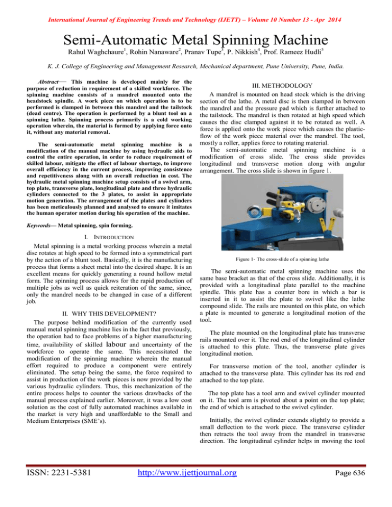
International Journal of Engineering Trends and Technology (IJETT) – Volume 10 Number 13 - Apr 2014 Semi-Automatic Metal Spinning Machine Rahul Waghchaure1, Rohin Nanaware2, Pranav Tupe3, P. Nikkish4, Prof. Rameez Hudli5 K. J. College of Engineering and Management Research, Mechanical department, Pune University, Pune, India. Abstract— This machine is developed mainly for the purpose of reduction in requirement of a skilled workforce. The spinning machine consists of a mandrel mounted onto the headstock spindle. A work piece on which operation is to be performed is clamped in between this mandrel and the tailstock (dead centre). The operation is performed by a blunt tool on a spinning lathe. Spinning process primarily is a cold working operation wherein, the material is formed by applying force onto it, without any material removal. The semi-automatic metal spinning machine is a modification of the manual machine by using hydraulic aids to control the entire operation, in order to reduce requirement of skilled labour, mitigate the effect of labour shortage, to improve overall efficiency in the current process, improving consistence and repetitiveness along with an overall reduction in cost. The hydraulic metal spinning machine setup consists of a swivel arm, top plate, transverse plate, longitudinal plate and three hydraulic cylinders connected to the 3 plates, to assist in appropriate motion generation. The arrangement of the plates and cylinders has been meticulously planned and analysed to ensure it imitates the human operator motion during his operation of the machine. III. METHODOLOGY A mandrel is mounted on head stock which is the driving section of the lathe. A metal disc is then clamped in between the mandrel and the pressure pad which is further attached to the tailstock. The mandrel is then rotated at high speed which causes the disc clamped against it to be rotated as well. A force is applied onto the work piece which causes the plasticflow of the work piece material over the mandrel. The tool, mostly a roller, applies force to rotating material. The semi-automatic metal spinning machine is a modification of cross slide. The cross slide provides longitudinal and transverse motion along with angular arrangement. The cross slide is shown in figure 1. Keywords— Metal spinning, spin forming. I. INTRODUCTION Metal spinning is a metal working process wherein a metal disc rotates at high speed to be formed into a symmetrical part by the action of a blunt tool. Basically, it is the manufacturing process that forms a sheet metal into the desired shape. It is an excellent means for quickly generating a round hollow metal form. The spinning process allows for the rapid production of multiple jobs as well as quick reiteration of the same, since, only the mandrel needs to be changed in case of a different job. II. WHY THIS DEVELOPMENT? The purpose behind modification of the currently used manual metal spinning machine lies in the fact that previously, the operation had to face problems of a higher manufacturing time, availability of skilled labour and uncertainty of the workforce to operate the same. This necessitated the modification of the spinning machine wherein the manual effort required to produce a component were entirely eliminated. The setup being the same, the force required to assist in production of the work pieces is now provided by the various hydraulic cylinders. Thus, this mechanization of the entire process helps to counter the various drawbacks of the manual process explained earlier. Moreover, it was a low cost solution as the cost of fully automated machines available in the market is very high and unaffordable to the Small and Medium Enterprises (SME’s). ISSN: 2231-5381 Figure 1- The cross-slide of a spinning lathe The semi-automatic metal spinning machine uses the same base bracket as that of the cross slide. Additionally, it is provided with a longitudinal plate parallel to the machine spindle. This plate has a counter bore in which a bar is inserted in it to assist the plate to swivel like the lathe compound slide. The rails are mounted on this plate, on which a plate is mounted to generate a longitudinal motion of the tool. The plate mounted on the longitudinal plate has transverse rails mounted over it. The rod end of the longitudinal cylinder is attached to this plate. Thus, the transverse plate gives longitudinal motion. For transverse motion of the tool, another cylinder is attached to the transverse plate. This cylinder has its rod end attached to the top plate. The top plate has a tool arm and swivel cylinder mounted on it. The tool arm is pivoted about a point on the top plate; the end of which is attached to the swivel cylinder. Initially, the swivel cylinder extends slightly to provide a small deflection to the work piece. The transverse cylinder then retracts the tool away from the mandrel in transverse direction. The longitudinal cylinder helps in moving the tool http://www.ijettjournal.org Page 636 International Journal of Engineering Trends and Technology (IJETT) – Volume 10 Number 13 - Apr 2014 along the axis of the spindle. This type of sequence ensures smoother flow of the work piece during operation. Figure 2 shows a CATIA model of a semi-automatic metal spinning machine. Hence, the force generated at the roller end can be calculated asX * 0.15 = 1 * 70 X = 466.67 Kg-f (1) Where, ‘X’ is the force in Kg-f generated at the roller end of the lever. Hence, 466.67Kg-f is the force applied by which the effective spinning occurs. B. Replacement by Hydraulic System Now, according to mechanical design (refer to figure 3 & 4, the leverage on the operator side is reduced from 1m to approximately 0.594m. Figure 2- The Semi-Automatic Metal Spinning Machine IV. RESULTS I. Calculations The following calculations are made with respect to figure 3. These calculations provide a superficial analysis for the selection of cylinders that can suit the size of the cross slide. A. Practical Observations According to practical visual interpretations, it has been observed that a normal human operator of 60-70 Kg can successfully spin a material as hard/tough as Stainless Steel (SS). SS is the toughest material that can be formed on the machine. At the time of spinning, it is observed that the operator tends to apply partially or completely his self-weight on to the lever as shown in image [3]. Figure 4- Machine operation using hydraulic force. So the force generated on the free end is calculated again, now that we know the spinning force is, 466.67 * 0.15 = 0.594 * P P = 117.84 Kg-f (2) Where, P is the force generated at the operator side after modification in of the mechanical design. From equations (1) and (2); it can be seen that due to decrease in leverage, the force needed for spinning increases drastically. By referring to various catalogues available in the market, the following two sizes of cylinders (refer Table I) were found Figure 3- Operation during manual Spinning to be most suitable for the modification in the cross-slide. TABLE I Piston Rod Piston Area mm mm mm2 Rod Area mm2 Operating Pressure Range 15 25 35 50 Push Pull Push Pull Push Pull Push Pull 50 16 19.64 2.01 294.56 2364.4 490.94 440.67 687.31 616.93 987.8 881.3 63 25 31.18 4.91 467.65 394.01 779.41 656.68 1091.18 919.35 1558 1313.36 The stroke of the cylinders can vary as per the type of work piece. However, we have already considered a modification of cross slide, so in this case, the stroke of the cylinders generally will not and should not exceed 0.35m as, further, the assembly of cylinders and other components will be affected. ISSN: 2231-5381 II. Other Recommendations This machine is recommended for industries like automobile, aerospace, defence industry where typical sheet metal working takes place in large quantity. This machine is also a good substitute in places where high automation is not possible and not required. http://www.ijettjournal.org Page 637 International Journal of Engineering Trends and Technology (IJETT) – Volume 10 Number 13 - Apr 2014 V. DISCUSSION To ensure proper flow of material, use of three cylinders has been done which provide their three respective motions, i.e. longitudinal, transverse and swivel. After the assembly of the machine it needs to be mounted on the spinning lathe. Thus, the modification of the machine is such that it doesn’t require major changes in the current setup of the spinning lathe. For this purpose, the specifications of the spinning lathe must be known before the design of the spinning machine. The design of all other components thus will also depend on the specifications of spinning lathe. Finally, the motion of the cylinders is controlled by simple push-button system. The hydraulic circuit may vary from the hydraulic circuit designer’s point of view. ACKNOWLEDGMENT We thank Mr. Y. G. Waghchaure (Proprietor- Special Equipments, Jejuri MIDC) for providing us with this opportunity to work in the development of this machine. We also thank our guide ‘Prof. Rameez Hudli’ for sharing with us his valuable knowledge and experience. We also would like to thank our Head of Department of Mechanical Engineering ‘Dr. Ajit. M. Kate’ for his constant support and encouragement. Lastly, we thank all those who have directly or indirectly helped us in the development of this machine. Figure 5- Modified machine setup with hydraulics VI. CONCLUSION The machine is a substitute where high automation is not possible and not required. The machine eliminates human efforts. For obtaining a fine degree of finish to the final product, three cylinders have been provided, i.e., longitudinal, transverse and swivel. The size of the machine essentially depends upon the specifications of the spinning lathe. REFERENCES Machine Design – R. S. Khurmi, J. K. Gupta (S. Chand Publications) Mechanical Engineering Materials – O. P. Khanna (Dhanpat Rai Publications) FDM- R. S. Vaishwanar, Rajesh Prasad and Subhash Chander Research Paper on “Metal forming: An Analysis of Spinning Process” by John Monaghan Manufacturing Processes for Engineering Materials- Serope Kalpakjian, Steven Schmid. Research Paper on “Analysis of Material Deformation and Wrinkling Failure”- Wang, Lin Research Paper on “Introduction to Aluminium as an Engineering Material”- M. H. Jacobs, University of Birmingham, UK. Catalogues on Hydraulic Cylinders by Dutta Industries Pvt. Ltd., Pune. Workshop Technology- S. K. Hajra Choudhury, A. K. Hajra Choudhury, Nirjhar Roy ISSN: 2231-5381 http://www.ijettjournal.org Page 638


