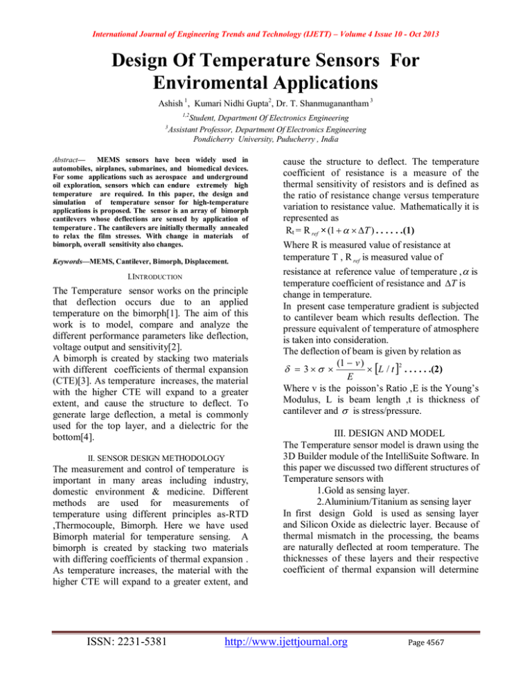
Design Of Temperature Sensors For Enviromental Applications
advertisement

International Journal of Engineering Trends and Technology (IJETT) – Volume 4 Issue 10 - Oct 2013 Design Of Temperature Sensors For Enviromental Applications Ashish 1 , Kumari Nidhi Gupta2, Dr. T. Shanmuganantham 3 1,2 3 Student, Department Of Electronics Engineering Assistant Professor, Department Of Electronics Engineering Pondicherry University, Puducherry , India Abstract— MEMS sensors have been widely used in automobiles, airplanes, submarines, and biomedical devices. For some applications such as aerospace and underground oil exploration, sensors which can endure extremely high temperature are required. In this paper, the design and simulation of temperature sensor for high-temperature applications is proposed. The sensor is an array of bimorph cantilevers whose deflections are sensed by application of temperature . The cantilevers are initially thermally annealed to relax the film stresses. With change in materials of bimorph, overall sensitivity also changes. Keywords—MEMS, Cantilever, Bimorph, Displacement. I.INTRODUCTION The Temperature sensor works on the principle that deflection occurs due to an applied temperature on the bimorph[1]. The aim of this work is to model, compare and analyze the different performance parameters like deflection, voltage output and sensitivity[2]. A bimorph is created by stacking two materials with different coefficients of thermal expansion (CTE)[3]. As temperature increases, the material with the higher CTE will expand to a greater extent, and cause the structure to deflect. To generate large deflection, a metal is commonly used for the top layer, and a dielectric for the bottom[4]. II. SENSOR DESIGN METHODOLOGY The measurement and control of temperature is important in many areas including industry, domestic environment & medicine. Different methods are used for measurements of temperature using different principles as-RTD ,Thermocouple, Bimorph. Here we have used Bimorph material for temperature sensing. A bimorph is created by stacking two materials with differing coefficients of thermal expansion . As temperature increases, the material with the higher CTE will expand to a greater extent, and ISSN: 2231-5381 cause the structure to deflect. The temperature coefficient of resistance is a measure of the thermal sensitivity of resistors and is defined as the ratio of resistance change versus temperature variation to resistance value. Mathematically it is represented as Rt = R ref × (1 T ) . . . . . .(1) Where R is measured value of resistance at temperature T , R ref is measured value of resistance at reference value of temperature , is temperature coefficient of resistance and T is change in temperature. In present case temperature gradient is subjected to cantilever beam which results deflection. The pressure equivalent of temperature of atmosphere is taken into consideration. The deflection of beam is given by relation as (1 v ) 2 3 L / t . . . . . .(2) E Where v is the poisson’s Ratio ,E is the Young’s Modulus, L is beam length ,t is thickness of cantilever and is stress/pressure. III. DESIGN AND MODEL The Temperature sensor model is drawn using the 3D Builder module of the IntelliSuite Software. In this paper we discussed two different structures of Temperature sensors with 1.Gold as sensing layer. 2.Aluminium/Titanium as sensing layer In first design Gold is used as sensing layer and Silicon Oxide as dielectric layer. Because of thermal mismatch in the processing, the beams are naturally deflected at room temperature. The thicknesses of these layers and their respective coefficient of thermal expansion will determine http://www.ijettjournal.org Page 4567 International Journal of Engineering Trends and Technology (IJETT) – Volume 4 Issue 10 - Oct 2013 the amount temperature. of deflection at a YOUNG MODULUS (µm) specific POISSON RATIO DENSITY ( gm/cc) (GPa) Substrate 100×50×5 Silicon 170 0.26 2.32 Dielectric 50×20×1 Silicon Oxide 73 0.17 2.2 Sensing Layer 50×20×1 Gold 74.48 0.42 19.32 Figure.1 Temperature Sensor Model-1 In second design Aluminum is used as sensing layer and Titanium layer is underneath the sensing layer. The thickness and materials should be selected so that the beams will be flat at the maximum desired operating temperature. TABLE-2 Dimension & Material Property of Model-2 LAYERS DIMENSION (µm) MATERIAL MATERIAL PROPERTY YOUNG MODULUS POISSON RATIO DENSITY ( gm/cc) (GPa) Substrate 100×100×10 Silicon 170 0.26 2.32 Dielectric 50×20×0.5 Sio2 PECVD_ECR 61 0.24 2.1 Sensing Layer 50×20×0.1 Titanium 115 0.3 4.51 50×20×0.3 Aluminium 70 0.36 2.7 Figure.2 Temperature Sensor Model-2 TABLE-3 Sensitivity Analysis of Temperature Sensor IV. RESULTS AND DISCUSSION The fabrication process and associated packaging are the main steps. The fabrication starts with a low-resistivity silicon wafer. A wet oxide film is thermally grown at the wafer to about 1.0 µm and then patterned with a buffered oxide etch .Subsequently, a layer of Gold is deposited on the wafer for sensing purpose for first design as stated in Table-1 and a layer of Aluminium/ Titanium for the second design as depicted in Table-2. With almost same dimension, sensitivity is calculated as ratio of output displacement to that of input temperature as explained in Table3. Input Tempe rature Existing Mode l Proposed Model (ᴼC) Displacement (µm) Se nsitivity (m/ᴼC) Displacement (µm) Se nsitivity (m/ᴼC) 10 1.02487 1.02487 e-7 1.37522 1.37522 e-7 20 2.07024 1.03512 e-7 2.77046 1.38523 e-7 30 3.11055 1.03685 e-7 4.18896 1.39632 e-7 40 4.14663 1.03665 e-7 5.95692 1.48923 e-7 50 5.19199 1.03839 e-7 7.83333 1.56662 e-7 60 6.23039 1.03839 e-7 9.49944 1.58324 e-7 TABLE-1 Dimension & Material Property of Model-1 LAYERS DIMENSION MATERIAL ISSN: 2231-5381 MATERIAL PROPERTY http://www.ijettjournal.org Page 4568 International Journal of Engineering Trends and Technology (IJETT) – Volume 4 Issue 10 - Oct 2013 SIMULATION RESULTS Sensitivity Analysis of Model 2 1.6 Sensitivity(10E -7/C ) 1. 55 1.5 1. 45 1.4 1. 35 10 Fig.3 15 20 25 30 35 40 Temperat ure(C) 45 50 55 60 Model-1 (10 ºC) V.CONCLUSION Fig.4 The effect of cantilever geometry, materials and dimensions on the sensitivity of a temperature sensor has been analyzed using INTELLISUITE as finite element based tool. The sensitivity analysis for different temperature ranges presents an idea to utilize a Silicon wafer area in an optimum manner, when designing cantilever type temperature sensors for different temperature ranges. From the analysis it is observed that Al/Ti metal shows better sensitivity than Gold as sensing layer. Model-1 (60ºC ) REFERENCES [1] .Sean Scott, Farshid Sadeghi, and Dimitrios Peroulis “An InherentlyRobust MEMS Temperature Sensor for Wireless Health Monitoring of Ball and Rolling Element Bearings”, Proceedings of IEEE Conference on Sensors, New Zealand ,vol.3, May 2009. Fig. 5 Model-2 (10ºC ) [2]. Aaron P. Gerratt, Sarah Bergbreiter, “Microfabrication of compliant all-polymer MEMS thermal actuators”, Sensors and Actuators : Physical Journal September 2011. [3]. Sean Scott, Joseph Katz, Farshid Sadeghi, and Dimitrios Peroulis, Member, “Highly Reliable MEMS Temperature Sensors for 275ºC Applications—Part 2:Creep and Cycling Performance”, Journal of Micromechanical System vol.no. 22, February 2013. [4].David Schmidt and Yingzi Lin “ Design of a Flexible MEMS Pressure and Temperature Sensing Film”, International Workshop on Advanced Smart Materials and Smart Structures Technology 2011, Dalian, China. Fig.6 Model-2 (50ºC) Sensitivity Analysis of Model 1 1.6 S e n sitivity(1 0 E -7 /C ) 1.55 1.5 1.45 1.4 1.35 10 15 20 25 30 35 40 Temperature(C) ISSN: 2231-5381 45 50 55 60 http://www.ijettjournal.org Page 4569 International Journal of Engineering Trends and Technology (IJETT) – Volume 4 Issue 10 - Oct 2013 ISSN: 2231-5381 http://www.ijettjournal.org Page 4570


