Efficient Implementation of Address Generator for WiMAX Deinterleaver with Different Modulation Schemes
advertisement

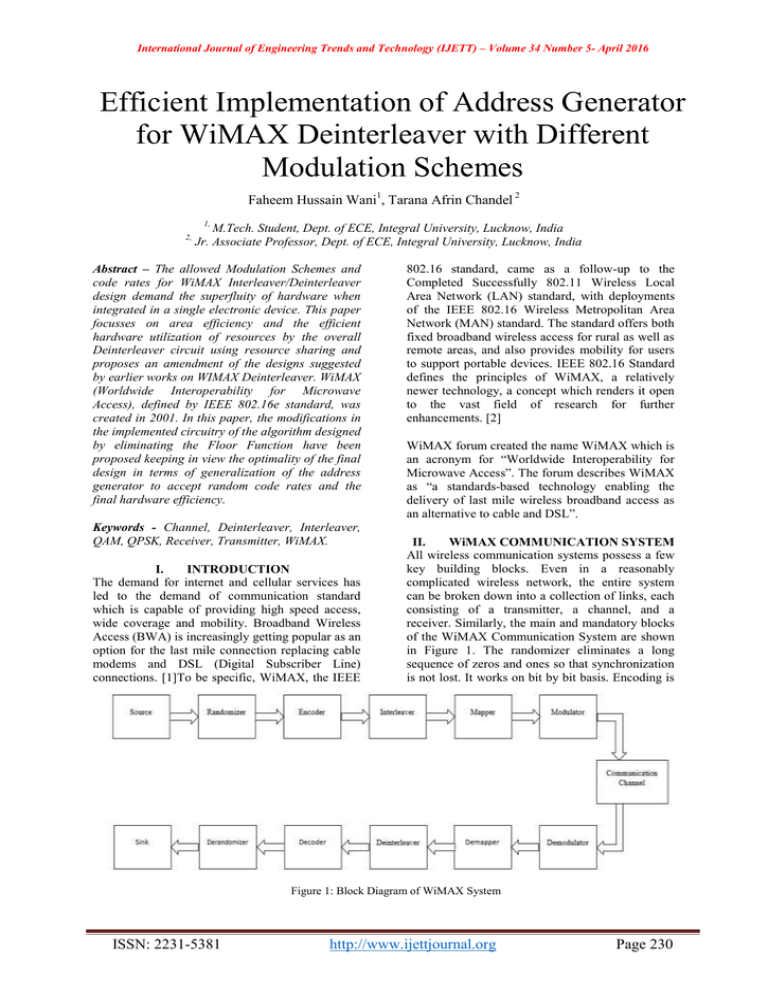
International Journal of Engineering Trends and Technology (IJETT) – Volume 34 Number 5- April 2016 Efficient Implementation of Address Generator for WiMAX Deinterleaver with Different Modulation Schemes Faheem Hussain Wani1, Tarana Afrin Chandel 2 1, 2, M.Tech. Student, Dept. of ECE, Integral University, Lucknow, India Jr. Associate Professor, Dept. of ECE, Integral University, Lucknow, India Abstract – The allowed Modulation Schemes and code rates for WiMAX Interleaver/Deinterleaver design demand the superfluity of hardware when integrated in a single electronic device. This paper focusses on area efficiency and the efficient hardware utilization of resources by the overall Deinterleaver circuit using resource sharing and proposes an amendment of the designs suggested by earlier works on WIMAX Deinterleaver. WiMAX (Worldwide Interoperability for Microwave Access), defined by IEEE 802.16e standard, was created in 2001. In this paper, the modifications in the implemented circuitry of the algorithm designed by eliminating the Floor Function have been proposed keeping in view the optimality of the final design in terms of generalization of the address generator to accept random code rates and the final hardware efficiency. Keywords - Channel, Deinterleaver, Interleaver, QAM, QPSK, Receiver, Transmitter, WiMAX. I. INTRODUCTION The demand for internet and cellular services has led to the demand of communication standard which is capable of providing high speed access, wide coverage and mobility. Broadband Wireless Access (BWA) is increasingly getting popular as an option for the last mile connection replacing cable modems and DSL (Digital Subscriber Line) connections. [1]To be specific, WiMAX, the IEEE 802.16 standard, came as a follow-up to the Completed Successfully 802.11 Wireless Local Area Network (LAN) standard, with deployments of the IEEE 802.16 Wireless Metropolitan Area Network (MAN) standard. The standard offers both fixed broadband wireless access for rural as well as remote areas, and also provides mobility for users to support portable devices. IEEE 802.16 Standard defines the principles of WiMAX, a relatively newer technology, a concept which renders it open to the vast field of research for further enhancements. [2] WiMAX forum created the name WiMAX which is an acronym for ―Worldwide Interoperability for Microwave Access‖. The forum describes WiMAX as ―a standards-based technology enabling the delivery of last mile wireless broadband access as an alternative to cable and DSL‖. II. WiMAX COMMUNICATION SYSTEM All wireless communication systems possess a few key building blocks. Even in a reasonably complicated wireless network, the entire system can be broken down into a collection of links, each consisting of a transmitter, a channel, and a receiver. Similarly, the main and mandatory blocks of the WiMAX Communication System are shown in Figure 1. The randomizer eliminates a long sequence of zeros and ones so that synchronization is not lost. It works on bit by bit basis. Encoding is Figure 1: Block Diagram of WiMAX System ISSN: 2231-5381 http://www.ijettjournal.org Page 230 International Journal of Engineering Trends and Technology (IJETT) – Volume 34 Number 5- April 2016 used for forward error correction where additional redundancy bits are added to the output of the randomizer. Interleaver is used for protection against burst errors which can make a sequence of consecutive bits erroneous, thus making it difficult for the error correcting codes to correct this long sequence of consecutive errors. WiMAX uses Reed Solomon Codes and its error correcting capacity is 8 bits. If there are more than 8 consecutive bits in error then RS code will not be able to correct them. It is the job of the interleaver to break this sequence of consecutive erroneous bits and make it possible to correct errors by RS codes. The mapper maps the incoming bits onto a constellation. The modulator is an Inverse Fast Fourier Transform device which converts its essentially digital inputs into analog outputs as the channel is analog in nature and cannot support the transmission of digital bits as such. Therefore the digital data has to be converted into an analog waveform before being transferred to the receiver through a channel which in most cases is free space. [1] WiMAX uses three modulation techniques in general which are mentioned below: * Quadrature Phase Shift Keying (QPSK) * 16-Quadrature Amplitude Modulation (16-QAM) *64-Quadrature Amplitude Modulation (64- QAM) III. TYPES OF WiMAX There are two types of usage models for WiMAX family of standards, firstly fixed usage model and secondly mobile usage model. The difference between these two systems is the ground speed at which the systems are designed to manage. Wireless access can be divided into three classes i.e. stationary, pedestrian and vehicular. The stationary and pedestrian classes are served by the fixed wireless access system and mobile wireless access system address the vehicular class. [3] A. Fixed WiMAX Fixed WiMAX is used to refer the systems built using 802.16-2004 (802.16) and the OFDM (Orthogonal Frequency Division Multiplexing) PHY as the air interface technology. Fixed WiMAX offers cost efficient point-to-point and point-to-multipoint solutions. [4] WiMAX provides fixed, portable or mobile non-line-of sight service from a base station to a subscriber station, known as customer premise equipment (CPE). B. Mobile WiMAX Mobile WiMAX is used to refer to system built using 802.16e-2005 and the OFDMA PHY as the air interface technology. Both fixed and mobile services are delivered by using mobile WiMAX implementations. Mobile WiMAX takes the fixed wireless application a step further and enables cell phone like applications on a much larger scale. ISSN: 2231-5381 Mobile WiMAX enables streaming video to be broadcast from a speeding police or other emergency vehicle at over 100 KMPH. It offers superior building penetration and improved securitymeasures over fixed WiMAX. It make users to roam between service areas. IV. INTERLEAVING IN WiMAX Interleaver and deinterleaver are reciprocal devices and a same gadget can be used for both the purposes. Fundamentally deinterleaver is a randomizer except that it does not change the state of the bits but works on the position of the bits i.e. it does not change a 1 to 0 or vice versa. All it does is that it defines a new address for every new incoming bit. Therefore the output of a deinterleaver is addresses which means that the output of the deinterleaver block is essentially a sequence of numbers. [5] The general diagram of WiMAX Deinterleaver is shown in Figure 2. Channel interleaver/deinterleaver has two memory blocks and an address generator. Memory blocks are indicated by M-1and M-2. Figure 2: Diagram of WiMAX Deinterleaver When one memory block is in write mode, the other will be in read mode and vice versa. The address generator generates the addresses. When select line (Sel) is 1, M-1 will be in write mode and M-2 will be in read mode. The upper multiplexer output will be write address and it is given to pin A of M-1. Simultaneously the lower multiplexer output will be read address and it is given to pin A of M-2. During this time the input data stream is written in M-1 as it receives the write addresses and simultaneously when read addresses are supplied to M-2, an interleaved data stream is read from it. According to interleaver depth, the memory blocks are written/read up to the desired location. After that the select line signal is swapped to read/write operation. [1]. The deinterleaver block of WiMAX makes use of different interleaving depths (Ncbps) to integrate http://www.ijettjournal.org Page 231 International Journal of Engineering Trends and Technology (IJETT) – Volume 34 Number 5- April 2016 various code rates and modulation. The data stream expected from the RS encoder is permuted by using the two-step processes labelled by Eqns. (1) and (2). These steps warrant mapping of coded bits onto nonadjacent subcarriers and alternate less/more significant bits of the modulation constellation, respectively. Thus, (1) (2) Here, the number of columns is represented by d (= 16 or 12 for WiMAX); mkand jkare the outputs after the first and second steps, respectively; and k varies from 0 to Ncbps − 1. s is a parameter defined as s = Ncpc/2, where Ncpc is the number of coded bits per subcarrier, i.e., 2, 4, or 6 for QPSK, 16-QAM, or 64-QAM, respectively [1]. Modulo and floor functions are signified by % and | |, respectively. The deinterleaver, which performs the inverse operation as of interleaver, is also defined by two permutations, indicated in Eqns. (3) and (4). Let mjand kjdefine the first and second level of permutations for the deinterleaver, where j is the index of received bits within a block of Ncbps bits. Thus, (3) (4) Hardware implementation of Address Generator for Deinterleaver using the floor function is very complex and munches bizarrely large amount of resources [6]. Conventional LUT-based technique is uninviting from many aspects such as slowness in operation, consumption of large logic resources leading to inefficiency in resource utilization, etc. For QAM-64 Modulation: (7) The algorithms for obtaining the addresses are developed from these above simplified equations representing all modulation schemes employed in WiMAX. [1] [6] [7] V. PROPOSED METHOD This paper proposes to modify the implemented circuitry for the above equations (5-7) keeping in view the optimality of the final design in terms of generalization of the address to be hardware and area efficient. The designing process has been divided into four modules. The first three modules deal with the designs of QPSK, 16-QAM and 64QAM address generators and the final module deals with the combination of these three modules using resource sharing. A divider and a subtractor circuit has been used as a common input module for all the three types of modulation schemes. Other common logic circuits are also shared. This resource sharing makes it possible to accept random code rates.The advantage of resource sharing is that it eliminates the use of multiple multiplexer modules as done in [1] and a single circuit can be used for all modules thereby further reducing the hardware, and improving the area efficiency. The Hardware Structure of the Address Generator for all modulation schemes is given below: The work proposed in [1] is efficient and better as compared to the floor function implementation or LUT Technique. These equations are given below for all the three modulation schemes employed in WiMAX Communication Systems: For QPSK Modulation: (5) For QAM -16 Modulation: (6) Figure 3: Hardware Structure of the Address Generator for QPSK ISSN: 2231-5381 http://www.ijettjournal.org Page 232 International Journal of Engineering Trends and Technology (IJETT) – Volume 34 Number 5- April 2016 The QPSK hardware shown in Fig. 3 has a row counter RWC0 to generate row numbers between 0 and d − 1. A column counter CLC0 with multiplexer M0 and comparator C0 generate the variable column numbers to implement permissible Ncbps. A multiplier ML0 and an adder A0 perform the desired operations to implement (5). The address generator for 16-QAM shown in Fig. 4 has a similar construction, as that of QPSK with few added modules. With the use of additional hardware in QAM-16, its design is extended to implementation of QAM-64, and is shown in Fig. 5. Figure 6: Complete Structure of Address Generator for WiMAX Deinterleaver VI. RESULTS This modified address generator was modelled in Xilinx ISE for all allowed modulation schemes in WiMAX and the simulation results were obtained by ISim Simulator. The Register Transfer Level (RTL) Schematic of the complete address generator is shown below in Fig.6. Figure 4: Hardware Structure of the Address Generator for QAM-16 Figure 6: RTL Schematic of Address Generator The Simulation results are shown in Fig. 7-9 for QPSK, QAM-16 and QAM-64 Modulation Schemes, respectively. Figure 5: Hardware Structure of the Address Generator for QAM-64 Figure 7: Simulation Results for QPSK ISSN: 2231-5381 http://www.ijettjournal.org Page 233 International Journal of Engineering Trends and Technology (IJETT) – Volume 34 Number 5- April 2016 The results have been compared with work [1] and the conventional LUT Technique. Comparative analysis is shown in Table 2. Table 2: Percentage of Device Utilization Device Specification Result of Proposed Technique Result of [1] LUT Technique [1] Slices 1% 3.49% 17.66% Flip-Flops 0.01% 0.5% 0.78% LUT’s 1% 3.35% 17.15% Maximum Operating Frequency 135.80 MHz 121.82 MHz 62.51 MHz Figure 8: Simulation Results for QAM-16 Figure 9: Simulation Results for QAM-64 The Verilog program of this address generator is targeted for Xilinx XC3S700A Device of Spartan 3A and 3AN Family. Table 1 shows the HDL Synthesis Report of Complete Address Generator. VII. CONCLUSION In this paper the Efficient Implementation of Address Generator of the WiMAX Deinterleaver has been proposed and it is an amendment to the work done in [1]. The Address Generator was implemented using the Verilog HDL for Xilinx FPGA. Comparative analysis of this work was done with the work done in[1] and with the Conventional LUT Technique is shown in Table 2. This design is efficient in consuming the hardware resources and thus takes comparatively lesser area upon FPGA Implementation. REFERENCES [1] Table 1: HDL Synthesis Report of Address Generator [2] [3] [4] [5] As depicted from the table 1 this particular address generator has the less device utilization than the existing models (Model proposed in [1] and the LUT Technique). So the efficiency will get increased due to the less utilization of the hardware as shown in Table 2. Also the maximum operating frequency of this design is greater than the value obtained for design proposed in [1]. ISSN: 2231-5381 [6] [7] Bijoy Kumar Upadhyaya, and Salil Kumar Sanyal, ―Efficient FPGA Implementation of Address Generator for WiMAX Deinterleaver, IEEE TRANSACTIONS ON CIRCUITS AND SYSTEMS—II: EXPRESS BRIEFS, VOL. 60, NO. 8, AUGUST 2013 B. Li, Y. Qin, C. P. Low, and C. L. Gwee, ―A survey on mobile WiMAX,‖ IEEE Commun. Mag., vol. 45, no. 12, pp. 70–75, Dec. 2007. M. N. Khan and S. Ghauri, ―TheWiMAX 802.16e physical layer model, in Proc. IET Int. Conf. Wireless, Mobile Multimedia Netw., Mumbai, India, 2008, pp. 117– 120. IEEE Standard for Local and Metropolitan Area Networks — Part 16: Air Interface for Fixed Broadband Wireless Access Systems—Amendment 2, IEEE Std. 802.16e 2005, 2005. Jaikaran Singh, Mukesh Tiwari, Deepak Dehriya ― An Amendment to FSM based Interleaver for WLAN and WiMAX in VHDL‖ . International Journal of Computer Applications (0975 – 8887) Volume 76– No.9, August 2013. B. K. Upadhyaya, I. S. Misra, and S. K. Sanyal, ``Novel design of address generator for WiMAX multimode interleaver using FPGA based finite state machine,'' in Proc. 13th Int. Conf. Comput. Inf. Technol., Dhaka, Bangladesh, 2010, pp. 153-158. Omar R, Gangadharaiah S.L. ―Hardware Efficient WiMAX Deinterleaver Capable of Address Generation forRandom Interleaving Depths‖,International Journal of Engineering Trends and Technology (IJETT), V10(4),187190 April 2014 http://www.ijettjournal.org Page 234


