A Design Analysis of MPLS VPN Core Ammar Al Mhdawi
advertisement
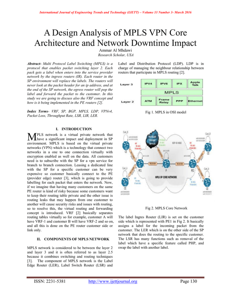
International Journal of Engineering Trends and Technology (IJETT) – Volume 33 Number 3- March 2016 A Design Analysis of MPLS VPN Core Architecture and Network Downtime Impact Ammar Al Mhdawi Research Scholar, USA Abstract- Multi Protocol Label Switching (MPLS) is a protocol that enables packet switching layer 2. Each pack gets a label when enters into the service provider network by the ingress routers (IR). Each router in the SP environment will replace the labels. The routers will never look at the packet header for an ip address, and at the end of the SP network, the egress router will pop the label and forward the packet to the customer. In this study we are going to discuss also the VRF concept and how is it being implemented in the PE routers [2]. Label and Distribution Protocol (LDP). LDP is in charge of managing the neighbour relationship between routers that participate in MPLS routing [2]. Index Terms- VRF, SP, BGP, MPLS, LDP, VPNv4, Packet Loss, Throughput Rate, LSR, LIR, LER. Fig 1. MPLS in OSI model I. INTRODUCTION M PLS network is a virtual private network that have a significant impact and deployment in SP environment. MPLS is based on the virtual private networks (VPN) which is a technology that connect two networks in a one to one connection virtually with encryption enabled as well on the data. All customers need is to subscribe with the SP for a vpn service for branch to branch connection. Leasing a dedicated line with the SP for a specific customer can be very expensive so customer basically connect to the PE (provider edge) router [3], which is going to provide labelling for each packet that enters the network. Now, if we imagine that having many customers on the same PE router is kind of risky because some customers want to keep their routing table private and the other issue is routing leaks that may happen from one customer to another will cause security risks and issues with routing, so to resolve this, the virtual routing and forwarding concept is introduced. VRF [2] basically separates routing tables virtually so for example, customer A will have VRF-1 and customer B will have VRF-2 and so on, and all this is done on the PE router customer side or link only. II. COMPONENTS OF MPLS NETWORK MPLS network is considered to be between the layer 2 and layer 3 and it is often referred to as layer 2.5 because it combines switching and routing techniques [3]. The component of MPLS network is the Label Edge Router (LER), Label Switch Router (LSR) and ISSN: 2231-5381 Fig 2. MPLS Core Network The label Ingres Router (LIR) is set on the customer side which is represented with PE1 in Fig 2. It basically assigns a label for the incoming packet from the customer. The LER which is on the other side of the SP network that does the routing to the specific customer. The LSR has many functions such as removal of the label which have a specific feature called PHP, and swap the label with another label. http://www.ijettjournal.org Page 130 International Journal of Engineering Trends and Technology (IJETT) – Volume 33 Number 3- March 2016 III. VIRTUAL ROUTING AND FORWARDING VRF is implemented in the provider edge (PE) routers. VRF table have the right information that provides reachability to the other side of the MPLS network using VPN tunnels. The interface that is facing the customer must be configured with VRF such as the following on cisco IOS: Cust_A#conf t Cust_A#(config-if) int TenGig 1/1 Cust_A#(config-if) ip vrf forwarding A-1 Note: this config will remove the ip address that is associated with Tengig 1/1, so it has to be entered again [1] Each VRF must associated with a route distinguisher value. For example, if Cust_A, Cust_B and Cust_C are advertising a 10.10.10.10 network, the only was that the other side of the MPLS network to know where to forward the traffic to what customer is by using the route distinguisher (RD). RD is a 64 bit in length, there are three types of it, type 0, 1 and 2. RD is just a flat number that is prepended to a route [5]. Below is example of configs showing RD assigned to VRFs using the two byte AS format [4]. Ip vrf Cust_A Rd 65002:20 ! Ip vrf Cust_B Rd 65002:30 ! Ip vrf Cust_C Rd 65002:40 ! Fig 3. Wireshark capture showing RT value IV. LABLES FORWARDING PROCESS For the MPLS to be forwarding packets, LDP must be enabled on each single router that part of the SP environment. The table below shows the label that assigned to each incoming route. Table 1. MPLS forwarding table with the local and outgoing tags When vpn routes are advertised among PE routes, the RD value will be included as part of the route. For example, a route to 192.168.10.2/24 in VRF Cust_C is advertised as 65002:40:192.168.10.2/24. The other concept is the route target (RT). They are applied to a VRF to control the import and export of routing within customers. The configuration is below: Ip vrf Cust_C Rd 65002:40 Route-target export 65000:100 Routes that are contained in VRF Cust_C will be exported using this value 65000:100. Wireshark pack capture examines the route target value as below: ISSN: 2231-5381 http://www.ijettjournal.org Page 131 International Journal of Engineering Trends and Technology (IJETT) – Volume 33 Number 3- March 2016 V. MPLS CONNECTION ISSUES Some of the common problem that may occur in the MPLA SP environment is: 1- Inactive LDP session (not started) 2- The labels are distributed but packets are not labled 3- LDP session started but no labels being assigned To solve these issues, a network engineer must examine the SP routers using the following steps: 1- Check LDP is enabled on the routers and check neighbours 2- Check for Cisco Express Forwarding (CEF) if enabled or not as it is very important for LDP activation process. 3- Make sure MPLS is enabled on every interface 4- Check for MPLS bindings and verify if they are exchanged. failure could happen so having redundant links is essential to pick up traffic in case of link outages. The business side may get effected when there is an outage. It could lead to losing revenue and reputation damage. Downtime cost may vary significantly within industries. Business size is the most obvious factor. Misconfiguration is the cause of the 60% of the outages that may occur in the SP environment due to changes made by engineers or network admins. Manual configuration mistakes can cost companies thousands of dollars per hour [7]. The graph below shows the cost consequences of an outage: Another issue that could lead to MPLS fail is MTU issues, were switches with no support of jumbo frames are up on the forwarding route. To make sure that the labels are being exchanged to reach the destination host, MPLS-aware trace route functionality must be used. Fig 5. Cost loss of a network outage for 41 companies (taken from reference [7] ) VI. LATENCY AND PACKET LOSS In a global network operation, WAN may carry applications that could be sensitive and critical to latency. For example, video calls and financial transactions are very sensitive to time. In reality, the distance of locations will always effect the throughput rate [6]. The greater the latency, the more delay that will be in the networks. In Fig 6., we can see the distance effect on the delay within cities and countries. Table 2. Latency of MPLS connections in different cities (taken from reference [6]). Fig 4. SP Network Architecture example As we can see in Fig 4. Above, there are many redundant link and connections. Many link flaps and ISSN: 2231-5381 http://www.ijettjournal.org Page 132 International Journal of Engineering Trends and Technology (IJETT) – Volume 33 Number 3- March 2016 When considering throughput rate, it is always important to know the packet loss rate and the delay when calculating the throughput. For example, for the latency of 200 ms rate and with 0.01% packet loss, the typical throughput is 0.73Mbps, but if we have 0.20% packet loss, then the throughput will drop to 0.16 Mbps, which is about 78% reductions from the previous value. Now we can see how the pack loss effect the throughput rate dramatically. In Fig 6. We can see the packet loss graph for different PL values. [2] Seno, Rahardianto., 2010., Perancangan dan Penerapan Technology Multi-Protocol Label Switching Pada Jaringan Telekomunikasi Indosat [3] Fitzgerald, Denis., 2012., Business Data Communications & Networking 11th Edition. [4] Osborne, Simha., 2002., Traffic Engineering with MPLS. [5] Ravi Ganesh V, M. V. Ramana Murthy . MPLS Traffic Engineering (An Implementation Framework), 2012. [6] Steve Garson., 2014., Low Latency Solutions., MPLSExperts.com [7] Evolven.com., 2014. Confronting system downtime. [8] Archana C” evaluation of RIPv2, OSPF, EIGRP Configuration on router the usage of CISCO Packet tracer”, International journal of Engineering science and innovative technology (IJESIT) volume 4, issue 2, pp. 215-222, March 2015 [9] www.cisco.com AUTHORS First Author – Ammar Al Mhdawi, Research Scholar and Network Engineer, MS Information Technology and Network Security, AIU, USA. BS in Computer Engineering, UOB. Fig 6. PL and throughput rate comparison (taken from reference [6]). VII. CONCLUSION In this paper, we have discussed the internal architecture of MPLS network. VRF has been discussed and provided the benefits of it. Explained RT and RD tags and their importance to the routes advertised by each customer. MPLS networks may face many issues such as LDP unpredicted states. Troubleshooting is required to reduce downtime that may cause loss of thousands of dollars in businesses. We can also say that MPLS VPN is scalable, efficient in terms of router CPU and BW usage. It reduces the time look up into the routing table using the CEF. For future work, more indepth analysis need to be discussed in the MPLS network as well as the quality of service effect on different customers. REFERENCES [1] Pultz, Richard., 2004., Analysis of MPLS-Based IP VPN Security: Comparison to Traditional L2VPNs such as ATM and Frame Relay, and Deployment Guidelines. ISSN: 2231-5381 http://www.ijettjournal.org Page 133
