Analysis of Boost Converter Using PI Control Algorithms
advertisement

International Journal of Engineering Trends and Technology- Volume3Issue2- 2012
Analysis of Boost Converter Using PI Control
Algorithms
Mitulkumar R. Dave1, K.C.Dave2
1
M.E. - II Year (Applied Instrumentation), Student
L.D.College of Engineering Ahmedabad, Gujarat, India-380015
2
Asst. Professor, Department of Instrumentation & Control Engineering,
L.D.College of Engineering Ahmedabad, Gujarat, India-380015
Abstract-- This paper explains about the boost converter and
control algorithm to reduce harmonics. For the improvement
of the functionality of the boost converter there are many
methods available among which I consider PI controller in
voltage mode control path. Initially I discussed the basic
function of the boost converter. Then I derived the transfer
function of the complete system. Then I considered model and
simulate into matlab without PI controller. Finally I used PI
controller in which the values of
and
has been derived
using the Ziegler-nichols method and loop shaping method. At
last the output response of the both methods is compared and
conclusion made upon that comparison.
II. BASIC FUNCTION OF BOOST CONVERTER
The DC/DC boost converter only needs four external
components: Inductor, Electronic switch, Diode and output
capacitor. The converter can therefore operate in the two
different modes depending on its energy storage capacity and
the relative length of the switching period.
Keywords -transfer function of boost converter; closed loop
system transfer function; Zigler-Nichols method; loop shaping
method.
I. INTRODUCTION
Today, most of the equipments are working on dc voltage
supply. Normally, the supply coming from power station to
the homes, offices, industries etc. is ac supply. So it is
needed to convert ac supply into D.C. supply to make useful
for the equipment which works on dc. The converter which
converts A.C. to D.C. is called ac-dc converter or rectifier.
A rectifier is a device used to convert alternating current to
direct current (rectification). Rectification is a process of
converting an alternating current or voltage into a direct
current or voltage. This conversion can be achieved by a
variety of circuits based on and using switching devices.
The widely used switching devices are diodes, thyristors,
power MOS, etc. [1].
Sometimes it is necessary to increases dc voltage. Boost
converter is a dc-dc converter in which the output voltage is
always greater than the input voltage which depends on
switching frequency [1]. Output voltage regulation in the
dc-dc converter is achieved by constantly adjusting the
amount of energy absorbed from the source and that injected
into the load, which is in turn controlled by the relative
durations of the absorption and injection intervals. These
two basic processes of energy absorption and injection
constitute a switching cycle [3].
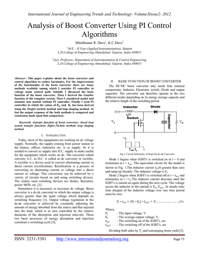
Fig.1 Circuit Schematic of Step-Up dc-dc Converter
Mode 1 begins when IGBT's is switched on at t = 0 and
terminates at t =
. The equivalent circuit for the model is
shown in Fig. 1.The inductor current (t) greater than zero
and ramp up linearly. The inductor voltage is .
Mode 2 begins when IGBT's is switched off at t =
and
terminates at t = .The inductor current decrease until the
IGBT's is turned on again during the next cycle. The voltage
across the inductor in this period is
. In steady state
time integral of the inductor voltage over one time period
must be zero.
∗
+( − )∗
Where,
: The input voltage, V.
: The average output voltage, V.
: The switching on of the IGBT's, sec
: The switching off of the IGBT's, sec
Dividing both sides by
ISSN: 2231-5381
= 0 … … … … … … … …(1)
http://www.internationaljournalssrg.org
and rearranging items yield [3].
Page 71
International Journal of Engineering Trends and Technology- Volume3Issue2- 2012
1
=
1−
=
. . … … … … … … … … … … … (2)
level. So for that purpose it is needed to use feedback loop
into the system that is shown in fig. 3.
Where,
: The switching period, s.
D : The duty cycle.
III. MATHEMATICAL EXPRESSION
A. Transfer Function of Boost Converter
Basic circuit of the boost converter is shown in Figure 2.
Here, L is the inductor and R is the resistor which is
consider as a load. is the current flow through the circuit.
Switch is triggered by the pulse which is generated by PWM
technique. Switch remains on during
cycle and off
during
cycle so triggering is depends on the duty cycle.
is the D.C. input voltage supply which is taken from the
bridge rectifier which converts A.C. input voltage into D.C.
output voltage.
is the output of the boost converter
which is larger than the input .
Fig. 3 Closed Loop System of Converter
( ) is given to the Pulse Width
In this fig. 3
Modulator. The output of the PWM is compared with
which is given to the PI controller. Then it is added with
which is given to the system.
From Figure
=
Taking
∗
∗
+
+
∗ e … … … … (7)
=0
+
∗
∗
+
∗
∗
∗
Fig. 2 Basic Circuit of Boost Converter
When switch turns on the current is passing through
switch which increases the current level in the inductor. At
the end of
time current stored into the inductor is . So,
=
∗
… … … … … … … … … … . . … … … . . ..(3)
Using Laplace Transformation,
(s) = L ∗ s ∗
From Figure
(s) … … … … … … … . … … ….(4)
can be given as
( )= ( )∗
… … … … … … … … … … … … ..(5)
From equation 4,
( )
( )
=
∗
… … … … … … … … … … … … … … … …(6)
Equation 6 is the basic Laplace transformation equation
of the boost converter.
B. Transfer Function of Closed Loop System
Now to achieve proper objective of converter, it is need
to measure and maintain output voltage at required voltage
ISSN: 2231-5381
=
∗
∗
[
{
∗
∗(
)∗
}]
=
… … … … …(8)
… … … … … ….(9)
Here, the equation 9 is the transfer function of the closed
loop system.
IV. SIMULATION
For the simulation purpose I considered the following
model:
Input Voltage (ac)
: 24 volt
Output Voltage (dc)
: 48 volt
Boost Inductor (L)
: 100 mH
Rated Power
: 16 W
Switching Frequency
: 1 kHz
Normally, duty cycle for boost converter is considered in
between 0.5 to 1. Selection of duty cycle depends on input
voltage supply and required output voltage [1].
When boost converter is used without using PI controller
it gives steady state error of 25%. So I used PI controller to
improve the performance of boost converter. To find out the
value of
and
, I used Ziegler-Nichols step response
method and Loop shaping method [4, 5].
Applying step function to the system and analyzing its
output response, I got two parameters L = 1 and T = 0.004.
http://www.internationaljournalssrg.org
Page 72
International Journal of Engineering Trends and Technology- Volume3Issue2- 2012
Using these, the value of
and
can be found by
Ziegler-Nichols method which is given below.
= 0.0036 and = 3.33
Now, applying these values into PI controller of the
closed loop system and simulate it into the matlab I got the
response as shown in fig. 4.
Fig. 5 Output Response of system using Loop shaping Method
Fig. 4 Output Response of system using Ziegler-Nichols Method
From above fig. 4 it is shown that it removes steady state
error but initially it provide high oscillations.
Now, using the Loop shaping method, eq. 9 and
parameter of the considered model I got the following two
relation [4 ,5].
2∗ ∗
3000 ∗
= 3000 ∗
=
− 750 … … … … … …(10)
… … … … … … … … … … … … ….(11)
For PI controller, is maintained at 0.7 and parameters
and
must be a larger [6]. So, using eq.10 and eq.11
= 2.68 and = 13146
Now, applying these values into PI controller of the
closed loop system and simulate it into the matlab I got the
response as shown in fig. 5.
From the fig. 5 it is shown that it reduce steady state error
and it doesn’t produce any oscillation which was presented
during the Ziegler-Nichols method. The performance of the
system is improved by the PI controller using loop shaping
method.
V. CONCLUSION
This paper represents analysis of the boost converter
using Ziegler-Nichols method and loop shaping method.
From the above result, following are the conclusion that can
be drawn from this paper.
Using the boost converter without PI controller, it
produces steady state error of 25%.
Boost converter used with PI controller applying
Ziegler-Nichols method removes steady state error after 2.5
sec. But it produce high oscillation and maximum peak
overshoot of 900% that shown in fig. 4. It also produced
14.5% of output ripple. So it is undesirable.
Boost converter used with PI controller applying
loop shaping method removes steady state error faster and
also removes oscillation which is shown in fig. 5. It also
produced only 0.5% output ripple which is lower than the
Ziegler-Nichols method.
So, from above conclusion can be made that loop shaping
method gives better response than the Ziegler-Nichols
method for the proposed model.
VI. REFRENCES
[1]
[2]
[3]
[4]
[5]
[6]
[7]
[8]
[9]
ISSN: 2231-5381
K.B.Khanchandani , and M.D.Singh, Power Electronics, New
Delhi:Tata Mcgrawhill, 2005.
Industries, Venable. "Current Mode Control."
Mohammed, B. M Hasaneen, and Adel A. Elbaset. "Design and
Simulation of DC-DC Boost Converter," 2008.
Astrom,and Hagglund ,PID Controllers,1988.
Copeland, Brain R. "The Design of PID Controllers using Ziegler
Nichols Tuning," 2008.
D.P.Eckman, Automatic Process Control. New Delhi: Wiley
Eastern,1992
Chen Zhou, and M.Jovanovic, "Design Trade-offs in Continuous
Current-Mode Controlled Boost Power-Factor Correction Circuit,"
Virginia, May 1992.
V.K.Mehta and Rohit Mehta, Principles of Power System, New
Delhi:S.Chand, 2008.
W.Erickson, Robert. "DC-DC Power Converter," Article in Wiley
Encyclopedia of Electrical and Electronics Engineering.
http://www.internationaljournalssrg.org
Page 73


