Speech Signal Analysis And Synthesis By Using LPC Technique M. Tech student,
advertisement
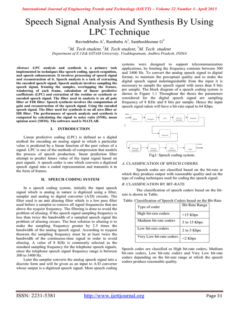
International Journal of Engineering Trends and Technology (IJETT) – Volume 22 Number 1- April 2015 Speech Signal Analysis And Synthesis By Using LPC Technique Ravindrbabu A1, Rambabu A2, Santhoshkumar G3 1 M. Tech student, 2M. Tech student, 3M. Tech student Department of E I E& GITAM University, Visakhapatnam, Andhra Pradesh, INDIA Abstract -LPC analysis and synthesis is a primary task implemented in techniques like speech coding, speech ecognition, and speech enhancement. It involves processing of speech signal and reconstruction of it. Speech analysis is a task of extracting the encoded speech signal. Speech analysis involves sampling the speech signal, framing the samples, overlapping the frames, windowing of each frame, calculation of linear predictive coefficients (LPC) and extraction of the residue or synthesis or encoded speech signal. The filter used in analysis is an all pole filter or FIR filter. Speech synthesis involves the computation of gain and reconstruction of the speech signal. Using the encoded speech signal. The filter used for synthesis is an all zero filter or IIR filter. The performance of speech analysis and synthesis is computed by calculating the signal to noise ratio (SNR), mean opinion score (MOS). The software used is MATLAB. I. systems were designed to support telecommunication applications, by limiting the frequency contents between 300 and 3400 Hz. To convert the analog speech signal to digital format, to maintain the perceptual quality and to make the digital speech signal indistinguishable from the input it is necessary to sample the speech signal with more than 8 bits per sample. The block diagram of a speech coding system is shown in Figure 1.1 Throughout the thesis the parameters considered for the digital speech signal are sampling frequency of 8 KHz and 8 bits per sample. Hence the input speech signal taken will have a bit-rate equal to 64 Kbps. INTRODUCTION Linear predictive coding (LPC) is defined as a digital method for encoding an analog signal in which a particular value is predicted by a linear function of the past values of a signal. LPC is one of the methods of compression that models the process of speech production. linear prediction filter attempt to predict future value of the input signal based on past signals. A speech coder is one which converts a digitized speech signal into a coded representation and transmits it in the form of frames. II. SPEECH CODING SYSTEM Fig1: Speech coding system. A. CLASSIFICATION OF SPEECH CODERS Speech codes are classified based on the bit-rate at which they produce output with reasonable quality and on the type of coding techniques used for coding the speech signal. B. CLASSIFICATION BY BIT-RATE In a speech coding system, initially the input speech signal which is analog in nature is digitized using a filter, sampler and analog to digital converter (A/D) circuits. The filter used is an anti aliasing filter which is a low pass filter used before a sampler to remove all signal frequencies that are above the nyquist frequency. The filtering is done to avoid the problem of aliasing. If the speech signal sampling frequency is less than twice the bandwidth of a sampled speech signal the problem of aliasing occurs. The best solution to aliasing is to make the sampling frequency greater by 2.5 times the bandwidth of the analog speech signal. According to nyquist theorem the sampling frequency must be at least twice the bandwidth of the continuous-time signal in order to avoid aliasing. A value of 8 KHz is commonly selected as the standard sampling frequency for the telephone speech signals, since the telephone speech signal frequency range is between 300 to 3400 Hz. Later the sampler converts the analog speech signal into a discrete form and will be given as an input to A/D converter whose output is a digitized speech signal. Most speech coding ISSN: 2231-5381 The classification of speech coders based on the bitrate is shown in Table. Table: Classification of Speech Coders based on the Bit-Rate Bit-Rate Range Type of coder High bit-rate coders >15 Kbps Medium bit-rate coders 5 to 15 Kbps Low bit-rate coders Very Low bit-rate coders 2 to 5 Kbps <2 Kbps Speech codes are classified as High bit-rate coders, Medium bit-rate coders, Low bit-rate coders and Very Low bit-rate coders depending on the bit-rate range at which the speech coders produce reasonable quality. http://www.ijettjournal.org Page 31 International Journal of Engineering Trends and Technology (IJETT) – Volume 22 Number 1- April 2015 III. CLASSIFICATION BY CODING TECHNIQUES Based on the type of coding technique used speech codes are classified into three types and are explained below. They are Waveform coders Parametric coders Hybrid coders A. WAVEFORM CODERS Waveform coders digitize the speech signal on a sampleby-sample basis. Its main goal is to make the output waveform to resemble the input waveform. So waveform coders retain good quality speech. Waveform coders are low complexity coders, which produce high quality speech at data rates above and around 16 Kbps. When the data rate is lowered below this value the reconstructed speech signal quality gets degrade. Waveform coders are not specific to speech signals and can be used for any type of signals. The two types of waveform coders are Time domain Waveform Coders and Frequency domain Waveform Coders. Time domain waveform coders utilize the digitization schemes based on the Time domain properties of the speech signal. Some of the examples of Time domain waveform coding techniques are Pulse Code Modulation (PCM), Differential Pulse Code Modulation (DPCM), Adaptive Differential Pulse Code Modulation (ADPCM) and Delta Modulation. Frequency domain waveform coders segment the speech signal into small frequency bands and each band is coded separately using waveform coders. In these coders, the accuracy of encoding is altered dynamically between the bands to suit the requirements of a speech waveform. Examples of frequency domain waveform coders are Sub band coders and Adaptive transform coders. B. PARAMETRIC CODERS In parametric coders the speech signal is assumed to be generated from a model which is controlled by some speech parameters. In these coders the speech signal is modeled using a limited number of parameters corresponding to the speech production mechanism. These parameters are obtained by analyzing the speech signal and quantizing before transmission. At the receiving end the decoder uses these parameters to reconstruct the original speech signal. In these coders the output speech signal is not an exact replica of the input speech signal and the resemblance of the input speech signal is lost. However, the output speech signal will utter the same as the input speech signal. Using parametric coders it is possible to obtain very low bit-rates (< 2.4 Kbps) at a reasonable quality. To retain the quality one has to use waveform coders taking advantage of the properties of both speech production and auditory mechanisms, so that the resulting quality is good at the cost of increased bit-rates compared to parametric coders. At lower bit-rates, the quality attained by the waveform coders is less compared to parametric coders. Examples of parametric coders are Linear Predictive Coders (LPC) and Mixed Excitation Linear Predictive (MELP) coders. This class of coders works well for low bit-rates. In these coders increasing the bit-rate does not ISSN: 2231-5381 result in an increase in the quality as it is restricted by the coder chosen. For this type of coders the bit-rate is in the range of 2 to 5 Kbps. C. HYBRID CODERS Hybrid coders try to fill the gap between waveform coders and parametric coders. Hybrid coders operate at medium bit-rates between those of waveform coders and parametric coders and produce high quality speech than parametric coders. There are a number of hybrid encoding schemes, which differ in the way the excitation parameters are generated. Some of these techniques quantize the residual signal directly, while others substitute approximated quantized waveforms selected from an available set of waveforms. A hybrid coder is a combination of both waveform coder and parametric coder. Like parametric coders, hybrid coders relies on the speech production model, as in waveform coders an attempt is made to match the original signal with the decoded signal in time domain. An example of hybrid coder is the Code Excited Linear Predictive (CELP) coders. We are generally produces two types of sounds Voiced sounds Un voiced sounds D. VOICED SOUNDS Voiced sounds are usually vowels and often have high average energy levels and very distinct resonant or formant frequencies. Voiced sounds are generated by air from the lungs being forced over the vocal cords. E. UNVOICED SOUNDS Unvoiced sounds are usually consonants and generally have less energy and higher frequencies then voiced sounds. The production of unvoiced sound involves air being forced through the vocal tract in a turbulent flow. F. MARTHA METICAL MODE OF SPEECH PRODUCTION In LPC analysis for each frame a decision-making process is made to conclude whether a frame is voiced or unvoiced. If the frame is voiced an impulse train is used to represent it with non zero taps occurring at intervals of the pitch period. In this thesis the method used for the estimation of the pitch period is the autocorrelation method. If the frame is considered as unvoiced the frame is represented using white noise and the pitch period is zero as the vocal cords do not vibrate. So the excitation to LPC filter is an impulse train or white noise. IV. LPC SPEECH ENCODING/ANALYSIS Analysis of speech signal is employed in variety of systems like voice recognition system and digital speech coding system. In encoding technique we are using sampling, framing, overlapping , windowing techniques are used. A. SAMPLING In sampling the continuous signal is converted to discrete signal. For example conversion of sound wave into the sequence of samples. http://www.ijettjournal.org Page 32 International Journal of Engineering Trends and Technology (IJETT) – Volume 22 Number 1- April 2015 V. LPC SYNTHESIS/DECODING The process of decoding a sequence of speech segments is the reverse of the encoding process. Each segment is decoded individually and the sequence of reproduced sound segments is joined together to represent the entire input speech signal. In synthesis we are using IIR filter. The transfer function of IIR filter is Fig2: sampling of signal B. FRAMING Normally a speech signal is not stationary, but seen from a short-time point of view it is. This result from the fact that the glottal system can’t change immediately. It is having n samples with signal frequency fs with time interval tst(stationary) then n=tstfs C. OVERLAPPING A. LPC MODEL The overlap add method is a efficient way to evaluate the discrete convolution of a very long signal is h(n). The concept is to divide the problem into multiple convolutions of h[n] with short segment of x[n]. The most preferable method for overlapping of frames is circular overlap add method. The particular source-filter model used in LPC is known as the linear predictive coding model. It has two key components: analysis or encoding and synthesis or decoding.The analysis part of LPC involves examining the speech signal and breaking it down into segments or blocks.The receiver performs LPC synthesis by using the answers received to build a filter that when provided the correct input source will be able to accurately reproduce the original speech signal.Essentially, LPC synthesis tries to imitate human speech production. D. WINDOWING In windowing we are mainly using hamming window because it have less disadvantages compared to other windows of rectangular, haning windows. In hamming window we have “raised cosine”. The “raised cosine” with these particular coefficients was proposed by Richard W. Hamming. We find it by using the formula w(n)= 0.54-0.46cos(2*п* n/N-1) E. CALCULATING LPC COEFFICIENTS The values for the reflection coefficients are used to define the digital lattice filter which acts as the vocal tract in this speech synthesis system. New values for k1-k10 are needed for every 25msec block of the utterance. The value for k1-k10 is derived from the LPC-10 coefficient value, so LPC value must be calculated first.LPC is based on linear equations to formulate a mathematical model of the human vocal tract and an ability to predict a speech sample based on previous ones. The vocal tract is modeled by an all pole transfer function of the form B. ANALYSIS/SYNTHESIS TECHNIQUES The transmitter or sender analyses the riginal signal and acquires parameters for the model which are sent to the receiver. The receiver then uses the model and the parameters it receives to synthesize an approximation of the original signal. VI. LPC APPLICATION In general, the most common usage for speech compression is in standard telephone system. Further applications of LPC and other speech compression schemes are voice mail systems telephone answering machines and multimedia applications. Most multimedia applications, unlike telephone applications, involve one-way communication and involve storing the data. VII. RESULTS Where p is the number of LPC coefficients, in our case p=10 And are the LPC coefficient values In order to calculate the LPC values for each 25msec block of the utterance, I used mat lab’s built in LPC function. Function LPC-coefficients=LPC (Y,P) Y is a 25 millisecond utterance P is the number of LPC coefficients (poles) Fig3: Input signal before overlap ISSN: 2231-5381 http://www.ijettjournal.org Page 33 International Journal of Engineering Trends and Technology (IJETT) – Volume 22 Number 1- April 2015 This is the input signal. It is plotted by taking time on Xaxis and amplitude on Y-axis. The blue shaded portion of the signal represents the energy present in the signal. Fig7: Synthesis signal after removing overlap. It represents the synthesis signal after removing overlapping. In this the number of frames are decreased. Fig4 : Input signal after overlap It is obtained by overlapping the frames of input signal. Due to overlapping, the number of frames in the signal is increased. Fig7: Window signal. It represents the Hamming windows signal which contains only the main lobe without containing any side lobes. Fig5: Analysis signal It represents the signal obtained after analysis or encoding. This signal is also called as the residue signal. It is obtained by passing the analysis signal through an FIR filter which is also called as “All pole filter”. VIII. CONCLUSION Linear predictive coding encoders break up a sound signal into different segments and then send information on each segment to the decoder. The encoder send information on whether the segment is voiced or unvoiced and the pitch period for voiced segment which is used to create an excitement signal in the decoder. The encoder also send information about the vocal tract which is used to build a filter on the decoder side which when given the excitement signal as input can reproduce the original speech. REFERENCES Fig6 :Synthesis signsl before remove overlap It represents the synthesis signal also called as decoded signal. It is obtained by passing the analysis signal through an IIR filter which is an “All zero filter”. 1. 2. 3. 4. ISSN: 2231-5381 Willaim H. Press, Brian P. Flannery, Saul A. Teukolsky, and Willaim T Vetterling. Numerical Recipies in C: “speech analysis and synthesis”. Cambridge University Press, Cambridge, England-1988. Steven F. Boll. “LPC analysis and synthesis” IEEE Transactions on Acoustics, Speech, and Signal Processing, ASSP-27(2):113-120, April 1979. J. Makhoul. “Linear predictive coding” A tutorial review. Proceedings of the IEEE, 63(4):561-580, April 1975. Thomas F Queteri, “Speech Processing”. http://www.ijettjournal.org Page 34 International Journal of Engineering Trends and Technology (IJETT) – Volume 22 Number 1- April 2015 5. 6. 7. 8. A.M.Kandoz, “low bit rate speech coding applications”. Emmanuel C. Ifeachor and Barrie W. Jervis. “Speech synthesis” Apractical approach. Addison-Wesley-1993. Kinjo, Funaki.K “Human Speech Recognition Based on Speech Analysis”IEEE Industrial Electronics, IECON 32nd Annual Conference on 2006. A.S. Spanias, “Speech coding: a tutorial review,” Proceedings of the IEEE, Vol 82, Issue 10, Oct 1994, pp. 1541–1582. ISSN: 2231-5381 http://www.ijettjournal.org Page 35

