Comparative Study of Microstrip Patch Antenna for Harish Langar , Bharti Gupta
advertisement
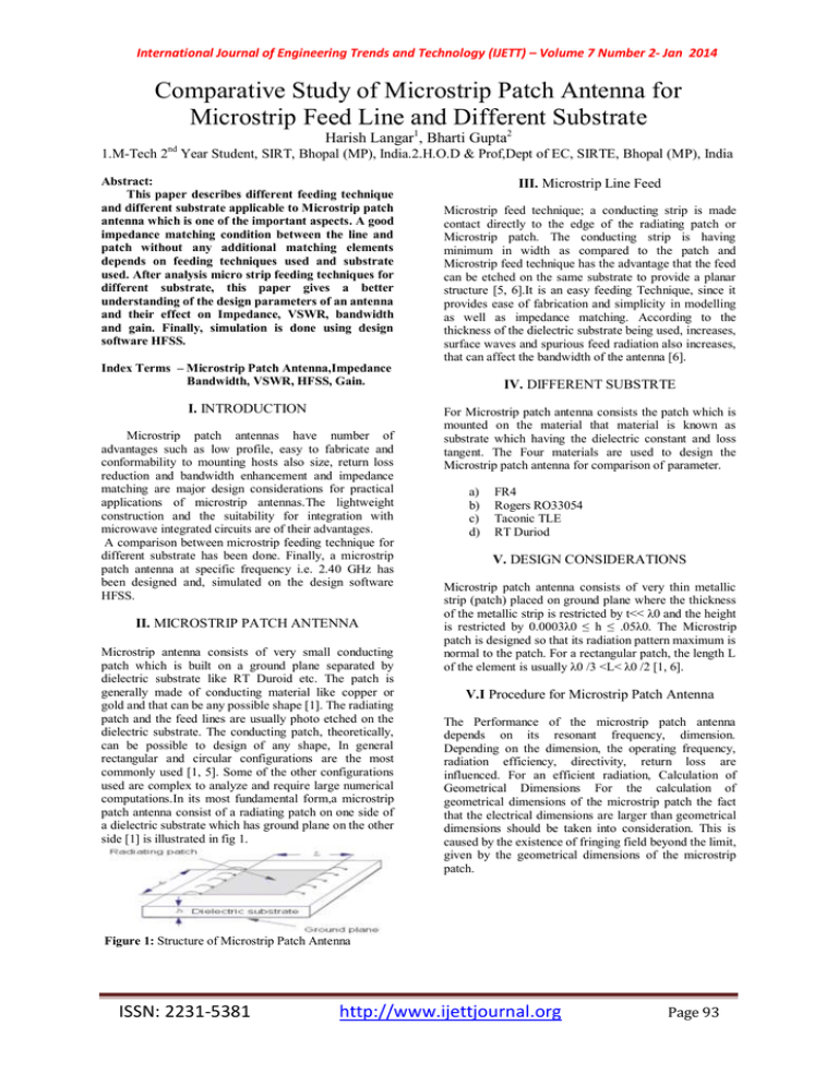
International Journal of Engineering Trends and Technology (IJETT) – Volume 7 Number 2- Jan 2014 Comparative Study of Microstrip Patch Antenna for Microstrip Feed Line and Different Substrate Harish Langar1, Bharti Gupta2 nd 1.M-Tech 2 Year Student, SIRT, Bhopal (MP), India.2.H.O.D & Prof,Dept of EC, SIRTE, Bhopal (MP), India Abstract: This paper describes different feeding technique and different substrate applicable to Microstrip patch antenna which is one of the important aspects. A good impedance matching condition between the line and patch without any additional matching elements depends on feeding techniques used and substrate used. After analysis micro strip feeding techniques for different substrate, this paper gives a better understanding of the design parameters of an antenna and their effect on Impedance, VSWR, bandwidth and gain. Finally, simulation is done using design software HFSS. Index Terms – Microstrip Patch Antenna,Impedance Bandwidth, VSWR, HFSS, Gain. I. INTRODUCTION Microstrip patch antennas have number of advantages such as low profile, easy to fabricate and conformability to mounting hosts also size, return loss reduction and bandwidth enhancement and impedance matching are major design considerations for practical applications of microstrip antennas.The lightweight construction and the suitability for integration with microwave integrated circuits are of their advantages. A comparison between microstrip feeding technique for different substrate has been done. Finally, a microstrip patch antenna at specific frequency i.e. 2.40 GHz has been designed and, simulated on the design software HFSS. II. MICROSTRIP PATCH ANTENNA Microstrip antenna consists of very small conducting patch which is built on a ground plane separated by dielectric substrate like RT Duroid etc. The patch is generally made of conducting material like copper or gold and that can be any possible shape [1]. The radiating patch and the feed lines are usually photo etched on the dielectric substrate. The conducting patch, theoretically, can be possible to design of any shape, In general rectangular and circular configurations are the most commonly used [1, 5]. Some of the other configurations used are complex to analyze and require large numerical computations.In its most fundamental form,a microstrip patch antenna consist of a radiating patch on one side of a dielectric substrate which has ground plane on the other side [1] is illustrated in fig 1. III. Microstrip Line Feed Microstrip feed technique; a conducting strip is made contact directly to the edge of the radiating patch or Microstrip patch. The conducting strip is having minimum in width as compared to the patch and Microstrip feed technique has the advantage that the feed can be etched on the same substrate to provide a planar structure [5, 6].It is an easy feeding Technique, since it provides ease of fabrication and simplicity in modelling as well as impedance matching. According to the thickness of the dielectric substrate being used, increases, surface waves and spurious feed radiation also increases, that can affect the bandwidth of the antenna [6]. IV. DIFFERENT SUBSTRTE For Microstrip patch antenna consists the patch which is mounted on the material that material is known as substrate which having the dielectric constant and loss tangent. The Four materials are used to design the Microstrip patch antenna for comparison of parameter. a) b) c) d) FR4 Rogers RO33054 Taconic TLE RT Duriod V. DESIGN CONSIDERATIONS Microstrip patch antenna consists of very thin metallic strip (patch) placed on ground plane where the thickness of the metallic strip is restricted by t<< λ0 and the height is restricted by 0.0003λ0 ≤ h ≤ .05λ0. The Microstrip patch is designed so that its radiation pattern maximum is normal to the patch. For a rectangular patch, the length L of the element is usually λ0 /3 <L< λ0 /2 [1, 6]. V.I Procedure for Microstrip Patch Antenna The Performance of the microstrip patch antenna depends on its resonant frequency, dimension. Depending on the dimension, the operating frequency, radiation efficiency, directivity, return loss are influenced. For an efficient radiation, Calculation of Geometrical Dimensions For the calculation of geometrical dimensions of the microstrip patch the fact that the electrical dimensions are larger than geometrical dimensions should be taken into consideration. This is caused by the existence of fringing field beyond the limit, given by the geometrical dimensions of the microstrip patch. Figure 1: Structure of Microstrip Patch Antenna ISSN: 2231-5381 http://www.ijettjournal.org Page 93 International Journal of Engineering Trends and Technology (IJETT) – Volume 7 Number 2- Jan 2014 (a) Calculated patch width W VI. DESIGNING c 2 2 f0 r 1 (1) (b) Calculated effective dielectric constant reff r 1 r 1 h 1 12 2 2 W 1/2 (2) (c) Calculated the extended incremental length ‘ L ’of the patch due to fringing effect W reff 0.3 0.264 h L 0.412h W reff 0.258 0.8 h (3) Figure 2 : RMSA Design of FR4 for microstrip feed (d) Calculated the patch effective length Leff Leff c 2 f 0 reff (4) (e) Calculated the patch actual length L Leff 2L (5) Figure 3 : RMSA Design of Rogers RO4350 for Microstrip feed. (f) Calculated Wavelength c 0 f0 (6) (g) Calculation of the ground plane dimensions for single patch (Lg and Wg): Lg = 6h+L and Wg = 6h+W (7) FR4 as the substrate with dielectric constant of 4.4. The rest of the basic parameters are: Resonant Frequency: fo = 2.4 GHz ,Substrate Permittivity: εr = 4.4 (FR4),Substrate Thickness: h = 1.6 mm ,Loss tangent: tan δ =0.002 ROGERS RO4350 as the substrate with dielectric constant of 3.66. The rest of the basic parameters are: Resonant Frequency: fo = 2.4 GHz,Substrate Permittivity: εr = 3.66 (ROGERS RO4350),Substrate Thickness: h = 1.6 mm,Loss tangent: tan δ =0.004 Figure 4 :RMSA Design of Taconic TLE for Microstrip feed TACONIC TLE as the substrate with dielectric constant of 2.95. The rest of the basic parameters are:Resonant Frequency: fo = 2.4 GHz,Substrate Permittivity: εr = 2.95 (TACONIC TLE),Substrate Thickness: h = 1.6 mm,Loss tangent: tan δ =0.0028 RT Duroid as the substrate with dielectric constant of 2.2. The rest of the basic parameters are:Resonant Frequency: fo = 2.4 GHz ,Substrate Permittivity: εr = 2.2 (RT Duroid),Substrate Thickness: h = 1.6 mm,Loss tangent: tan δ =0.0009 from this calculation Microstrip patch antenna design in hfss software for two feed line and four substrate. ISSN: 2231-5381 Figure 5 : RMSA Design of Rogers RT Duriod for Microstrip feed http://www.ijettjournal.org Page 94 International Journal of Engineering Trends and Technology (IJETT) – Volume 7 Number 2- Jan 2014 XY Plot 1 VI.SIMULATION RESULT HFSSModel1 0.00 ANSOFT Curve Info dB(S(LumpPort1,LumpPort1)) Setup1 : Sw eep2 VI.I For Microtrip Feed. -5.00 HFSSModel1 ANSOFT Curve Info -10.00 dB(S(LumpPort1,LumpPort1)) Setup1 : Sw eep2 -2.50 dB(S(LumpPort1,LumpPort1)) Name -5.00 X Name dB(S(LumpPort1,LumpPort1)) XY Plot 1 0.00 X Y m1 2.3675 -10.0205 m2 2.4410 -10.1112 m3 2.4094 -24.9608 m1 m2 -15.00 Y m1 2.3851 -14.0777 m2 2.3460 -9.9816 m3 2.4170 -10.0073 -20.00 -7.50 m3 m2 -25.00 m3 1.00 1.25 1.50 1.75 -10.00 2.00 Freq [GHz] 2.25 2.50 2.75 3.00 Figure 10: S11 graph of RMSA Teconic TLE -12.50 m1 XY Plot 2 1.00 1.25 1.50 1.75 2.00 Freq [GHz] 2.25 2.50 2.75 VSWR(LumpPort1) Setup1 : Sw eep2 140.00 XY Plot 2 HFSSModel1 120.00 ANSOFT 120.00 Curve Info m1 X VSWR(LumpPort1) Setup1 : Sw eep2 Y Name VSWR(LumpPort1) Name 100.00 2.3851 1.4945 100.00 80.00 VSWR(LumpPort1) ANSOFT Curve Info 3.00 Figure 6: S11 graph of RMSA FR4 X m1 Y 2.4094 1.3409 80.00 60.00 40.00 60.00 20.00 m1 0.00 40.00 1.00 1.25 1.50 1.75 2.00 Freq [GHz] 2.25 2.50 2.75 3.00 Figure 11: VSWR Graph of Taconic TLE 20.00 XY Plot 1 m1 1.00 1.25 1.50 1.75 2.00 Freq [GHz] 2.25 2.50 2.75 dB(S(LumpPort1,LumpPort1)) Setup1 : Sw eep2 -2.50 HFSSModel1 ANSOFT Curve Info dB(S(LumpPort1,LumpPort1)) Setup1 : Sw eep2 -2.50 -5.00 Y m1 2.4228 -12.3077 m2 2.4480 -10.0963 m3 2.3989 -9.9778 dB(S(LumpPort1,LumpPort1)) XY Plot 1 0.00 X ANSOFT Curve Info 3.00 Figure 7: VSWR graph of RMSA FR4 Name HFSSModel1 0.00 0.00 dB(S(LumpPort1,LumpPort1)) HFSSModel1 160.00 -15.00 -5.00 Name -7.50 X Y m6 2.4094 -16.7362 m7 2.4362 -9.9191 m8 2.3699 -9.9586 m8 m7 -10.00 -12.50 -7.50 m3 m2 -15.00 -10.00 m6 m1 -12.50 -17.50 1.00 1.25 1.50 1.75 2.00 Freq [GHz] 2.25 2.50 2.75 3.00 Figure 12: S11 graph of RMSA RT Duroid -15.00 -17.50 1.00 1.25 1.50 1.75 2.00 Freq [GHz] 2.25 2.50 2.75 XY Plot 2 3.00 HFSSModel1 150.00 Figure 8: S11 graph of RMSA Rogers RO4350 ANSOFT Curve Info VSWR(LumpPort1) Setup1 : Sw eep2 XY Plot 2 HFSSModel1 125.00 ANSOFT Name 125.00 m2 Curve Info X Y 2.4094 1.1198 VSWR(LumpPort1) Setup1 : Sw eep2 100.00 VSWR(LumpPort1) 100.00 m2 X Y VSWR(LumpPort1) Name 2.4228 1.6401 75.00 75.00 50.00 50.00 25.00 25.00 m2 0.00 1.00 m2 0.00 1.00 1.25 1.50 1.75 2.00 Freq [GHz] 2.25 2.50 2.75 3.00 1.25 1.50 1.75 2.00 Freq [GHz] 2.25 2.50 Figure 13: VSWR graph of RMSA RT Duroid Figure 9: VSWR graph of RMSA Rogers RO4350 ISSN: 2231-5381 2.75 http://www.ijettjournal.org Page 95 3.00 International Journal of Engineering Trends and Technology (IJETT) – Volume 7 Number 2- Jan 2014 VI.II. Result of Microstrip Feed for Different Substrates at 2.4 GHz frequency Substrate Resonant Freq(s) [GHz] VSWR BW (MHz) Gain (dB) Impedance R+jX FR4 Rogers RO4350 Taconic TLE 2.40 2.40 1.631 1.916 71 49.1 0.330 1.732 2.40 1.340 66.3 2.874 RT Duroid 5880 2.40 1.198 73.5 3.323 32.75+j9.54 34.96j22.89 37.29j0.124 44.79+j1.25 8 VII. Conclusion Rogers RT Duroid 5880 is the best among the 4 substrates chosen as it has lowest loss tangent Rogers RT Duroid 5880 gives best result in comparison to all the 4 substrates for microstrip feed. microstrip feed as a better match is achieved resulting in better BW and gain. References: [1] Kashwan K R ,Rajeshkumar V, Gunasekaran T and Shankar Kumar K R, “Design and Characterization of Pin Fed Microstrip Patch Antennae”, IEEE proceedings of FSKD’2011 [2] Jagdish. M. Rathod, Member, IACSIT, IETE (I), IE (I), BES (I) ,“Comparative Study of Microstrip Patch Antenna for Wireless Communication Application”, IJIMT, Vol. 1, No. 2, June 2010 [3 ] Govardhani.Immadi, M.S.R.S Tejaswi, M.Venkata Narayana,” Design of Coaxial fed Microstrip Patch Antenna for 2.4GHz BLUETOOTH Applications,Journal of Emerging Trends in Computing and Information Sciences VOL. 2, NO. 12, December 2011. [4 ] P.J.Soh, M.K.A.Rahim, A.Asrokin, M.Z.A.Abdul Aziz, “Design, modeling and performance comparison of different feedingtechniques for a microstrip patch antenna”, Journal technology in university technology Malaysia, 47(D) Dis.2007 103-120. [5] C. A. Balanis, 1982, Antenna Engineering, 2nd ed., Willey. [6] Ahmed Fatthi Alsager Design and Analysis of Microstrip Patch Antenna Arrays thesis comprises 30 ECTS credits and is a compulsory part in the Master of Sciencewith a Major in Electrical Engineering Communication and Signal processing.Thesis No. 1/2011 ISSN: 2231-5381 http://www.ijettjournal.org Page 96


