Stress Failure Location Prediction of Kickstand Using CATIA V5 Analysis
advertisement

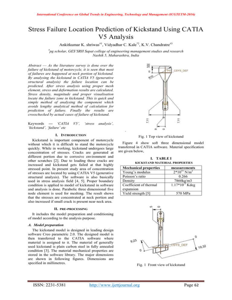
International Conference on Global Trends in Engineering, Technology and Management (ICGTETM-2016) Stress Failure Location Prediction of Kickstand Using CATIA V5 Analysis Ankitkumar K. shriwas#1, Vidyadhar C. Kale*2, K.V. Chandratre#3 # pg scholar, GES’SRH Sapat college of engineering management studies and research Nashik 5, Maharashtra, India Abstract — As the literature survey is done over the failure of kickstand of motorcycle, it is seen that most of failures are happened at neck portion of kickstand. By analysing the kickstand in CATIA V5 (generative structural analysis) the failure location can be predicted. After stress analysis using proper mesh element, stress and deformation results are calculated. Stress density, magnitude and proper visualisation locate the failure zone in kickstand. This is quick and simple method of analysing the component which avoids lengthy analytical method of calculation for prediction of failure. Finally the results are crosschecked by actual cases of failure of kickstand. Keywords — ‘CATIA ‘kickstand’, ‘failure’ etc V5’, ‘stress analysis’, . I. INTRODUCTION Kickstand is important component of motorcycle without which it is difficult to stand the motorcycle quickly. While in working, kickstand undergoes large concentration of stresses. Cracks are generated at different portion due to corrosive environment and other scratches [2]. Due to loading these cracks are increased and kickstand gets failed at that highly stressed point. In present study area of concentration of stresses are located by using CATIA V5 (generative structural analysis). The software is also basically used in stress analysis field [4, 5]. Proper boundary condition is applied to model of kickstand in software and analysis is done. Parabolic three dimensional five node element is used for meshing. The result shows that the stresses are concentrated at neck portion and also increased if small crack is present near neck area. Fig. 1 Top view of kickstand Figure 4 show soft three dimensional model transferred in CATIA software. Material specification are given below, I. TABLE I KICKSTAND MATERIAL PROPERTIES Mechanical properties Young’s modulus Poisson’s ratio Density Coefficient of thermal expansion Yield strength [5] measurements 2*1011 N/m2 0.266 7860kg/m3 1.17*10-5 Kdeg 570 MPa II. PRE-PROCESSING It includes the model preparation and conditioning of model according to the analysis purpose. A. Model preparation The kickstand model is designed in leading design software Creo parametric 2.0. The designed model is then transferred to the CATIA software where material is assigned to it. The material of generally used kickstand is plain carbon steel in fully annealed condition [3]. The material mechanical properties are stored in the software library. The major dimensions are shown in following figures. Dimensions are specified in millimetres. ISSN: 2231-5381 Fig. 1 Front view of kickstand http://www.ijettjournal.org Page 62 International Conference on Global Trends in Engineering, Technology and Management (ICGTETM-2016) Fig. 3 Side view of kickstand Fig. 4 Three dimensional model of kickstand in CATIA V5 B. Meshing The model is meshed using parabolic tetrahedron (three dimensional) element. The error in meshing are minimised by selecting parabolic element as hourglass effect is minimum in parabolic element [1]. Near about 2600 element are formed for analysis purpose. C. Boundary condition The kickstand is constrained at different position for different motion (degree of freedom). While analysing the actual kickstand in applied position, the portion that contacts the ground is free to move. The neck arms are fastened to motorcycle chassis by nut bolt hence all degree of freedom of both arm are locked. In CATIA, at arm of kickstand clamp is provided. Smooth virtual part is provided at the recess of bolt in arm portion because during deformation the holes don’t get deformed. For simplicity new UCS system is defined to apply the boundary condition. Following figure shows the kickstand model after applied boundary condition [1]. surface contact between kickstand and ground. Sometimes due to excess loading on motorcycle in parked position one arm get forced. This force is applied by outgrowth of chassis as shown in figure. The kickstand undergoes in static loading as it is used in static system [6]. Normal reaction over the kickstand varies as the weight of motorcycle varies. The reaction is also increased if rider sits over the motorcycle in actuated position of kickstand. When the motorcycle is parked on kickstand, balancing is done as three point support standing. Force exerted by kickstand on ground is calculated practically and found average as 245.25 N. F = μ * Rn Where, μ: coefficient of friction between steel and concrete about 0.4 [7]. Rn: normal reaction about 245.25 N. F = 98.1 N Force over one pin where spring is tied is 189.51 N and 50.78 N in horizontal direction. Other shock load and spring load is small hence doesn’t affect the stress behaviour of kickstand. In steady applied position kickstand undergoes two main forces that are frictional force and ground reaction. After applying loading condition the model looks like following figure, Fig. 6 Loading at the bottom of kickstand Fig. 7 Loading over the pin of kickstand Fig. 5 Constraint at the neck of kickstand D. Loading conditions During the leaning position of the motorcycle, ground reaction is acted on the kickstand at the contacting point with ground. This is vertically upward directed. Frictional force is also acted at the ISSN: 2231-5381 II. PROCESSING Now the kickstand is ready for analysis purpose. In CATIA (generative structural analysis) processing is done by solver which is already provided in their workstation. Gauss R6 method is used for solution calculation. Material analysis, meshing, stiffness calculation, load and constraint determination is done stepwise in solver and results are calculated [1]. Complete model for processing is shown below, http://www.ijettjournal.org Page 63 International Conference on Global Trends in Engineering, Technology and Management (ICGTETM-2016) Fig. 8 Complete model for analysis III. POST PROCESSING In post processing the results that are obtained in processing are analysed. Von misses criteria of failure is most accurate criteria among other failure criteria, hence it is used for analysis of kickstand [2]. It is seen that most of stresses are generated in neck portion of the kickstand as shown in figure. About 1.24*108 N/m2 maximum stresses are generated at neck portion. Perhaps this value is much lesser than yield strength of plain carbon steel as provided in table of properties. Hence kickstand doesn’t fails but during long service of kickstand dents and corroded areas are formed at different areas of kickstand which lowers strength of material and the crack are generated at these most vulnerable areas of kickstand. Fig. 11 Stress concentration at frame number 21 At frame 40, Fig. 12 Stress concentration at frame number 40 It is seen from the above figures, the first evidence of stress is near to the neck portion of the kickstand. Principle stresses that are generated in all over the kickstand are shown in following figure, Fig. 9 Von mises stresses generated in kickstand When the stresses are starts generating, at different frame following visualization is seen as, At frame 12, Fig. 13 Principle stress distribution in kickstand For more stress behaviour information cut section is taken along the middle surface of the kickstand as shown in the following figure, Fig. 10 Stress concentration at frame number 12 At frame 21, Fig. 14 Longitudinal sectional view of kickstand with generated stress Complete meshed model along with stress contour is shown below, ISSN: 2231-5381 http://www.ijettjournal.org Page 64 International Conference on Global Trends in Engineering, Technology and Management (ICGTETM-2016) Fig. 15 Meshed model along with stress contour In actual case studies of failure of kickstand it also seen that kickstand is generally failed or starts failing near the neck area. Following are some real photograph of failure of kickstand. Fig. 19 Ductile failure of another kickstand Fig. 16 Failure of kickstand at neck [3] From results and case studies it is found proper boundary and loading conditions generates the stresses near the neck portion of the kickstand. Though the stresses are less initially but after a long service time of kickstand the material weakens, these stresses are increased beyond the strength of kickstand material and crack is formed near the neck of kickstand and then kickstand fails as ductile failure. Weakening of material is mainly due to corrosion and dents as kickstand is direct contact with the environment. Fig. 17 Side view of failure part of kickstand [3] Fig. 20 Stress magnitude in the kickstand IV. CONCLUSIONS It is found from result and discussion that the most vulnerable site for failure of kickstand is neck portion of kickstand. During actuated position of kickstand most stresses are generated near the neck of kickstand. From this result it is seen that for quick and simple checking of stress and failure analysis CATIA V5 is suitable software than the lengthy analytical method of stress calculations. Pin and bottom surface are less prone to stress concentration than the neck as the results are verified in software and case studies. REFERENCES Fig. 18 Failure of another kickstand [1] [2] [3] ISSN: 2231-5381 R. Cozzens, CATAI V5 workbook, 19th ed., SDC publication, Cedar city, Utah, 2009 V.B. Bhandari, design of machine element, 3rd ed., tata McGraw-hill education, new Delhi, india, 2010 Z. huda, K.w. Shi, R. Bulpett, ‘failure analysis of steel motorcycle kickstand’, journal of failure analysis and prevention, vol. 9, pp 305-309, may 2009 http://www.ijettjournal.org Page 65 International Conference on Global Trends in Engineering, Technology and Management (ICGTETM-2016) [4] [5] A.J. Muminovik, I. Sarc, N. Repcic, ‘numerical analysis of stress concentration factor’, procedia engineering, vol. 100, pp 707-713, 2015 M.A.M. Azlan, M.A.M. Nor, H. Rashid, W.M.F.W. Mahyuddin, J. Mahud, ‘stress analysis of low loader chassis’, procedia engineering, vol. 41, pp 995-1001, 2012 ISSN: 2231-5381 [6] [7] D. Kopernic, ‘on the safety of motorcycle side stands’, SAE technical papers series, vol. 2, N4, 840905, pp1-9, 1984 (2015) Coefficient of friction super civil-CD, http://www.supercivilcd.com/FRICTION.htm http://www.ijettjournal.org Page 66


