Spatiotemporal Segregation-Pattern Drift in Particle-Laden Rimming Flow Guyez and P. J. Thomas *
advertisement

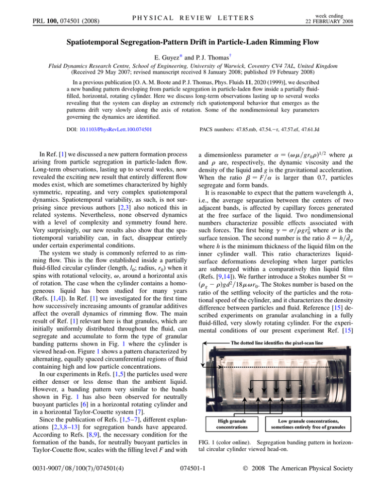
PRL 100, 074501 (2008) PHYSICAL REVIEW LETTERS week ending 22 FEBRUARY 2008 Spatiotemporal Segregation-Pattern Drift in Particle-Laden Rimming Flow E. Guyez* and P. J. Thomas† Fluid Dynamics Research Centre, School of Engineering, University of Warwick, Coventry CV4 7AL, United Kingdom (Received 29 May 2007; revised manuscript received 8 January 2008; published 19 February 2008) In a previous publication [O. A. M. Boote and P. J. Thomas, Phys. Fluids 11, 2020 (1999)], we described a new banding pattern developing from particle segregation in particle-laden flow inside a partially fluidfilled, horizontal, rotating cylinder. Here we discuss long-term observations lasting up to several weeks revealing that the system can display an extremely rich spatiotemporal behavior that emerges as the patterns drift very slowly along the axis of rotation. Some of the nondimensional key parameters governing the dynamics are identified. DOI: 10.1103/PhysRevLett.100.074501 PACS numbers: 47.85.mb, 47.54.r, 47.57.ef, 47.61.Jd In Ref. [1] we discussed a new pattern formation process arising from particle segregation in particle-laden flow. Long-term observations, lasting up to several weeks, now revealed the exciting new result that entirely different flow modes exist, which are sometimes characterized by highly symmetric, repeating, and very complex spatiotemporal dynamics. Spatiotemporal variability, as such, is not surprising since previous authors [2,3] also noticed this in related systems. Nevertheless, none observed dynamics with a level of complexity and symmetry found here. Very surprisingly, our new results also show that the spatiotemporal variability can, in fact, disappear entirely under certain experimental conditions. The system we study is commonly referred to as rimming flow. This is the flow established inside a partially fluid-filled circular cylinder (length, l0 ; radius, r0 ) when it spins with rotational velocity, !, around a horizontal axis of rotation. The case when the cylinder contains a homogeneous liquid has been studied for many years (Refs. [1,4]). In Ref. [1] we investigated for the first time how successively increasing amounts of granular additives affect the overall dynamics of rimming flow. The main result of Ref. [1] relevant here is that granules, which are initially uniformly distributed throughout the fluid, can segregate and accumulate to form the type of granular banding patterns shown in Fig. 1 where the cylinder is viewed head-on. Figure 1 shows a pattern characterized by alternating, equally spaced circumferential regions of fluid containing high and low particle concentrations. In our experiments in Refs. [1,5] the particles used were either denser or less dense than the ambient liquid. However, a banding pattern very similar to the bands shown in Fig. 1 has also been observed for neutrally buoyant particles [6] in a horizontal rotating cylinder and in a horizontal Taylor-Couette system [7]. Since the publication of Refs. [1,5–7], different explanations [2,3,8–13] for segregation bands have appeared. According to Refs. [8,9], the necessary condition for the formation of the bands, for neutrally buoyant particles in Taylor-Couette flow, scales with the filling level F and with 0031-9007=08=100(7)=074501(4) a dimensionless parameter !=gr0 1=2 where and are, respectively, the dynamic viscosity and the density of the liquid and g is the gravitational acceleration. When the ratio F= is larger than 0.7, particles segregate and form bands. It is reasonable to expect that the pattern wavelength , i.e., the average separation between the centers of two adjacent bands, is affected by capillary forces generated at the free surface of the liquid. Two nondimensional numbers characterize possible effects associated with such forces. The first being =gr20 where is the surface tension. The second number is the ratio h=dp where h is the minimum thickness of the liquid film on the inner cylinder wall. This ratio characterizes liquidsurface deformations developing when larger particles are submerged within a comparatively thin liquid film (Refs. [9,14]). We further introduce a Stokes number St g gd2 =18!r0 . The Stokes number is based on the ratio of the settling velocity of the particles and the rotational speed of the cylinder, and it characterizes the density difference between particles and fluid. Reference [15] described experiments on granular avalanching in a fully fluid-filled, very slowly rotating cylinder. For the experimental conditions of our present experiment Ref. [15] FIG. 1 (color online). Segregation banding pattern in horizontal circular cylinder viewed head-on. 074501-1 © 2008 The American Physical Society PRL 100, 074501 (2008) PHYSICAL REVIEW LETTERS suggests avalanche times of approximately 30 minutes. Since this is substantially longer than the longest rotation period of about 2 minutes of our cylinder, we can exclude effects due to avalanching. Direct observations of the flow also confirm immediately that the type of avalanching discussed in Ref. [15] is not a relevant mechanism in the present experiments. In Refs. [1,5] we used only one rotating cylinder of length l0 27 cm and radius r0 5:0 cm. In order to explore whether the granule bands display a dependence on r0 , as would be expected on the basis of the parameter , we conducted experiments with cylinders of different radii. The finite cylinder length almost certainly affects the flow dynamics, and, hence, we concurrently adjusted l0 to keep l0 =r0 5:4 constant. We monitored the flow by taking photographs, of the type shown in Fig. 1, at regular intervals, t, of the order of a few seconds or minutes and over total periods lasting up to four weeks. For each digital photograph, we scanned and extracted a horizontal pixel line, at a position corresponding approximately to that indicated in Fig. 1. Each pixelscan line was processed such that the location of the bands with high particle concentrations are represented in black, whereas regions with low particle concentrations appear in white. The successive pixel-scan lines for a photo sequence were then composed into a single image. This yields a space-time diagram revealing the drift of the banding patterns and, thereby, illustrates the overall system dynamics. Typical space-time diagrams are shown in Figs. 2 and 3(a)–3(c); the associated experimental conditions are summarized in Table I. The abscissa displays the spatial position L along the pixel-scan line (see Fig. 1). The ordinate displays time t, nondimensionalized by the rotation period, T 2 =!. Hence, t=T !t=2 represents the total number of cylinder revolutions. The experiments were conducted at temperature 21 0:5 C using silicone fluid (Ambersil, F111=500) with viscosity 480 m Pa s, surface tension 21:3 mN m1 , and density 1:106 g cm3 . For all experiments, the filling fraction F is 14.1% and is always small enough to ensure > 0:7 so that granules segregate as predicted by Ref. [9]. The granules used are spherical glass particles (density g 2:5 g cm3 ) at a concentration of 0:08 liter of particles per liter of fluid. Two particle samples were used: one contained particles with diameters 150 m dp 250 m and a mean diameter of dp 200 m, while the other sample had corresponding values of 250 m dp 425 m and dp 338 m. The samples were selected to ensure comparable . Figure 2(a) shows data for an experiment running over 1.5 days. It can be seen that the segregation bands drift outwards, i.e., towards the left and right cylinder end walls. The drift velocity increases as the end walls are approached. Figure 2(b) represents a magnification of the region 0 cm L 13 cm and 0 t=T 1000 of Fig. 2(a). week ending 22 FEBRUARY 2008 FIG. 2. Spatiotemporal diagrams illustrating band drift; for experimental conditions see Table I. The figure reveals how new bands continuously emerge after regular temporal intervals and at certain well-defined positions L. This enlarged region is representative for the entire space-time domain in Fig. 2(a). From Fig. 2(a) one estimates a maximum drift interval of about l0 =2 13:5 cm in 0.5 days. This implies drift velocities of the order of 3:125 m s1 . Note that the continuous generation of bands along the cylinder axis necessitates the existence of an axial granule back transport directed from the end walls towards the cylinder center. This replaces those granules moving within the bands towards the wall. Otherwise a continuous generation of new bands would not be possible because of the limited amount of granules contained inside the cylinder. The granule back transport probably takes place at the bottom of the pool of liquid inside the cylinder. However, since associated typical velocities must be of the order of the band-drift velocity, they cannot be observed easily by visual inspection. Patterns similar to those in Fig. 2 were found for experiments with 0:25 ! 1 rad s1 (0:015 0:033 and 0:004 St 0:014); all other parameters kept constant. When the rotation speed is reduced below approximately 0:25 rad s1 , entirely different dynamics emerge. 074501-2 PRL 100, 074501 (2008) week ending 22 FEBRUARY 2008 PHYSICAL REVIEW LETTERS TABLE I. Summary of experimental conditions for the results displayed in Fig. 2 and 3. Figure Figure Figure Figure Figure FIG. 3. Spatiotemporal diagrams illustrating band drift; for experimental conditions see Table I. Grey region in (b) and (c) due to obstructed view of camera. A typical space-time diagram for such an experiment, running over 25 days, is displayed in Fig. 3(a). Contrary to Fig. 2, here the segregation bands drift from the cylinder end walls towards its center. The average drift velocity is about l0 =2=25 days 6:25 108 m s1 , while the instantaneous drift velocity decreases with time. The figure appears to suggest that a stationary state may be approached after the 25-day period. (Note that for 1 104 t=T 2 104 some data are missing; the camera had turned off for about 2 days. The actual experiment continued running unaffected.) Figure 3(a) also reveals instances where two bands merge to form one single band; band 2 3(a) 3(b) 3(c) r0 (cm) 5.0 5.0 2.5 2.5 0.0008 0.0008 0.0031 0.0031 dp (m) 338 338 200 200 St ! (rad=s) 1.88 0.007 0.88 0.023 0.65 0.040 0.55 0.055 0.52 0.15 0.06 0.05 0.023 0.013 0.011 0.010 merging is not present in Fig. 2(a). Similar to Fig. 2(a), the continuous generation of new bands at the end walls requires an axial granule back transport, here directed towards the end walls. Figures 3(b) and 3(c) show results obtained in a cylinder that is smaller than that used for the experiments of Figs. 2 and 3(a). Figure 3(b) reveals the very surprising result that the segregation bands did essentially not move at all in 3 days. An identical evolution was found when increasing the rotation speed to give 0:011 0:033 (with associated values 1:54 0:41 and 0:04 St 0:005). This is almost the same , , and St intervals for which the larger cylinder in Figs. 2 and 3(a) displayed very complex behavior. Consequently, the changed behavior must be attributed to the increased cylinder curvature (larger ). When the rotation rate of the small cylinder with r0 2:5 cm was further reduced, the dynamics changed once again to adopt the essentially entirely irregular behavior displayed in Fig. 3(c). The drift direction of individual bands can alternate between left and right in time, and no clear pattern evolved over 3.5 days. Note that we have checked the reproducibility of our space-time plots by repeating a number of experiments. In all cases it was found that the data from multiple runs yielded qualitatively similar space-time plots. This indicates that the particular flow mode adopted is not sensitive to the initial conditions. The data in Fig. 2 clearly reveal that the dynamics repeat themselves in space and time. To characterize the behavior quantitatively, we performed series of Fourier analysis of the pixel intensities, It, at locations L along the pixelscan line. Each spectra was found to display a number of frequency peaks for each location L. These frequency peaks, which characterize the rates at which bands pass locations L, are displayed in Fig. 4. The figure shows a symmetric frequency distribution, which was found to become flatter for other experiments with increasing values of . Note that frequencies in Fig. 4 change in a sequence of discrete steps. The increase of the frequencies for L ! 0 cm and L ! 27 cm reflects higher rates of bands passing particular locations, L, near the end walls; as is anticipated from inspection of Fig. 2. Figure 5(a) displays the mean pattern wavelength as a function of time, t=T, for the experiment of Fig. 2. The minimum wavelength is about 1.7 cm and grows to a maximum value of 3 cm within t=T 300 revolu- 074501-3 PHYSICAL REVIEW LETTERS PRL 100, 074501 (2008) FIG. 4. Peak frequency of the Fourier spectra of the pixel intensities, It, as a function of the spatial position L. tions (here approximately 50 min). The wavelength increase is followed by an almost abrupt return to the minimum wavelength upon which the whole cycle surprisingly continuously repeats itself. Inspection of Fig. 2(a) reveals that the increase of with t=T is due to bands continuously disappearing at the end walls. Similarly, the sudden decrease reflects the simultaneous appearance of new bands at the various, well-defined, locations between the end walls and the cylinder center. The repetition time, =T, at which the wavelengthgrowth cycle repeats itself, is displayed in Fig. 5(b) as a function of . The data obtained for the left and right cylinder halves are displayed separately. Figure 5(b) reveals good left-right symmetry. Only the data points at 0:033 differ in the two sides of the cylinder. One crucial open question evidently concerns the physical mechanism initiating the particle-band drift; none of the existing theories [2,3,8–13] for the particle-band formation can account for it. In Fig. 2 the drift velocity increases as the bands approach the end walls, whereas it 2500 1000 3 800 400 τ/T τ / T 1.5 t (h) 2 t/T 600 Right side Left side 2000 2.5 1500 1000 1 200 0 1.5 a) 500 0.5 2 2.5 λ (cm) 3 0 3.5 0 0.01 b) 0.017 0.024 0.031 α FIG. 5. (a) Mean pattern wavelength as a function of the nondimensional time, t=T. (b) Nondimensional repetition time, =T, as a function of . Vertical line identifies boundary for band drift towards ( < 0:011) and away ( < 0:011) from end walls. week ending 22 FEBRUARY 2008 decreases in Fig. 3(a) as they drift away from them. This observation may indicate that the end walls play a crucial part in initiating the band drift. However, if this was the case, why do bands drift in opposite directions in Figs. 2 and 3(a)? Why is there irregular and oscillating drift in Fig. 3(c), and why is band drift essentially absent in Fig. 3(b)? However, the present data did indicate the important result that the different drift modes are adopted in defined intervals of the Stokes number, St, and of the ratio (influence of the surface tension according to the cylinder curvature). Hence, these two parameters appear to play key roles. This implies, in turn, that band drift arises as a natural consequence of the underlying fundamental flow physics governing the system and not as a result of imperfections of the apparatus. We conclude with a brief general comment regarding the theoretical models [2,3,8–13] for the granule-band formation that appeared since the publication of Ref. [5]. While the present data do not permit comments concerning these models, it is pointed out that none of the models captures the triplet-band fine structure reported in Ref. [5]. This implies either that the mechanism for granule-band formation for our experiment is different from the mechanisms in the experiments relating to [2,3,8–13] or, alternatively, that none of the existing models is complete. *E.M.C.Guyez@warwick.ac.uk † PJT1@eng.warwick.ac.uk [1] O. A. M. Boote and P. J. Thomas, Phys. Fluids 11, 2020 (1999). [2] B. D. Timberlake and J. F. Morris, Phys. Fluids 14, 1580 (2002). [3] G. Seiden, M. Ungarish, and S. G. Lipson, Phys. Rev. E 72, 021407 (2005). [4] S. T. Thoroddsen and L. Mahadevan, Exp. Fluids 23, 1 (1997). [5] P. J. Thomas, G. D. Riddell, S. Kooner, and G. P. King, Phys. Fluids 13, 2720 (2001). [6] M. Tirumkudulu, A. Mileo, and A. Acrivos, Phys. Fluids 12, 1615 (2000). [7] M. Tirumkudulu, A. Tripathi, and A. Acrivos, Phys. Fluids 11, 507 (1999). [8] B. Jin and A. Acrivos, Phys. Fluids 16, 633 (2004). [9] B. Jin and A. Acrivos, Phys. Fluids 16, 641 (2004). [10] B. D. Timberlake and J. F. Morris, Phil. Trans. R. Soc. A 361, 895 (2003). [11] R. Govindarajan, P. R. Nott, and S. Ramaswamy, Phys. Fluids 13, 3517 (2001). [12] A. Acrivos, Phys. Fluids 14, 3750 (2002). [13] J. Lee and A. J. C. Ladd, Phys. Rev. Lett. 95, 048001 (2005). [14] M. Tirumkudulu and A. Acrivos, Phys. Fluids 13, 14 (2001). [15] S. Courrech du Pont, P. Gondret, B. Perrin, and M. Rabaud, Phys. Rev. Lett. 90, 044301 (2003). 074501-4


