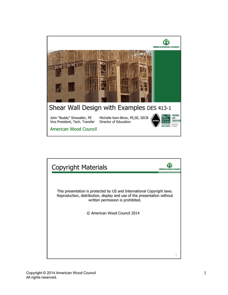
Shear Wall Design with Examples
John “Buddy” Showalter, PE
Vice President, Tech. Transfer
DES 413-1
Michelle Kam-Biron, PE,SE, SECB
Director of Education
American Wood Council
Copyright Materials
This presentation is protected by US and International Copyright laws.
laws
Reproduction, distribution, display and use of the presentation without
written permission is prohibited.
© American Wood Council 2014
2
Copyright © 2014 American Wood Council
All rights reserved.
1
Learning Objectives
• At the end of this program, participants will be better able to:
• Identify and understand the basic shear wall
system to resist lateral loads
• Understand the difference between segmented
and perforated shear wall design
• Understand hold down design
• Identify and analyze shear walls per the IBC,
WFCM, and SDPWS and understand the
differences between them
3
Outline
• Shear Walls Design Examples:
• 2012 IBC/IRC
/
Recognition
g
• 2012 WFCM Prescriptive
• 2012 WFCM Engineered
• 2008 SDPWS
4
Copyright © 2014 American Wood Council
All rights reserved.
2
AWC Design Standards
5
WFCM and IRC/IBC
2012 WFCM is referenced in 2012 IRC/IBC
6
Copyright © 2014 American Wood Council
All rights reserved.
3
WFCM and IRC
IRC R301.1.1 Alternative Provisions
7
WFCM and IRC
IRC R301.2.1.1 Wind limitations
8
Copyright © 2014 American Wood Council
All rights reserved.
4
WFCM and IBC
IBC Chapter 16
9
WFCM and IBC
IBC Section 2301.2
10
Copyright © 2014 American Wood Council
All rights reserved.
5
WFCM and IBC
IBC Section 2308
11
2012 WFCM
• Wood Frame Construction Manual
• 2012 WFCM uses ASCE 7-10 wind design
g provisions
p
12
Copyright © 2014 American Wood Council
All rights reserved.
6
ASCE 7-05 vs ASCE 7-10
13
SDPWS and IBC
2012 SDPWS is referenced in 2012 IBC
14
Copyright © 2014 American Wood Council
All rights reserved.
7
Outline
• 2012 IBC/IRC Recognition
• 2012 WFCM Prescriptive
• 2012 WFCM Engineered
• 2008 SDPWS
20
Segmented Shear Wall Method
21
Copyright © 2014 American Wood Council
All rights reserved.
8
Perforated Shear Wall Method
22
WFCM Prescriptive
NOTE:
•Wind Speeds 110-195 mph Exp. B & C
•Segmented & Perforated Shear Walls
•Other Application Limits
23
Copyright © 2014 American Wood Council
All rights reserved.
9
Design Example
Assumptions
• 130 mph (700-yr, 3-second gust) Exposure B
• L
L=36’
36
• W=30’
• 5/12 roof pitch
• Top plate to ridge = 6.25’
• 2-story
• 8’ wall height
g
• 6’8” door height
• 4’ window height
• Wood Structural Panel Exterior Sheathing
• Vary interior walls – with and without gypsum
24
Design Example
Design first floor shear wall
25
Copyright © 2014 American Wood Council
All rights reserved.
10
WFCM Prescriptive
2012 WFCM Prescriptive – Segmented
Interpolate = 12.3'
26
WFCM Prescriptive
2012 WFCM Prescriptive – Segmented
Interpolate = 0.68
Adjusted = 12.3' (0.68) = 8.4'
27
Copyright © 2014 American Wood Council
All rights reserved.
11
WFCM Prescriptive
2012 WFCM Prescriptive – Segmented – required = 8.4'
4’ + 4’ + 2.5’ + 2.5’ = 13’ > 8.4’ OK
Assumes gypsum on interior
28
WFCM Prescriptive
2012 WFCM Prescriptive – Segmented
29
Copyright © 2014 American Wood Council
All rights reserved.
12
WFCM Prescriptive
2001 WFCM Prescriptive – Segmented
What if we don’t count the gypsum on interior?
8.4’ x 1.3 = 10.9’
30
WFCM Prescriptive
2012 WFCM Prescriptive Segmented – required = 10.9'
Segmented shear wall – assuming no interior gypsum
4’ + 2.5’ + 2.5’ + 4’ = 13' > 10.9' OK
31
Copyright © 2014 American Wood Council
All rights reserved.
13
WFCM Prescriptive
2012 WFCM Prescriptive Segmented – Hold-downs
With and Without Gypsum
Segmented shear wall – requires hold downs on each segment
32
WFCM Prescriptive
2012 WFCM Prescriptive – Perforated Shear Wall (PSW)
% Full-height sheathing
8.4' / 36' = 23%
Interpolated = 1.86
8.4'(1.86) = 15.6'
w/ gypsum
10.9' / 36' = 30%
Interpolated = 1.72
10 9'(1
10.9
(1.72)
72) = 18.7
18 7'
w/o gypsum
21' Full-height sheathing > 18.7' OK
33
Copyright © 2014 American Wood Council
All rights reserved.
14
WFCM Prescriptive
2012 WFCM Prescriptive – Perforated
PSW requires fully sheathed wall
34
WFCM Prescriptive
2012 WFCM Prescriptive – Perforated – Hold-downs
PSW requires hold-downs only at the ends
35
Copyright © 2014 American Wood Council
All rights reserved.
15
WFCM Prescriptive
2012 WFCM Prescriptive – Perforated – Hold-downs
Hold-downs
= 3,488
3 488 lbs
w/ gypsum
3,488 / 1.3
= 2,683 lbs
w/o gypsum
•
•
•
Need to combine with top floor hold-down requirements
Based on capacity of first shear wall panel
Does not include dead load
36
Outline
• 2012 IBC/IRC Recognition
• 2012 WFCM Prescriptive
• 2012 WFCM Engineered
• 2008 SDPWS
37
Copyright © 2014 American Wood Council
All rights reserved.
16
WFCM Engineered
2012 WFCM Engineered
wrooff = 94 plf
wfloor = 128(0.82)*=105 plf
wtotal = 199 plf
199(30')/2
=2,985 lbs
*Footnote 2: (H+1)/11
adjustment = (8+1)/11
38
WFCM Engineered
2012 WFCM Engineered – Segmented
39
Copyright © 2014 American Wood Council
All rights reserved.
17
WFCM Engineered
2012 WFCM Engineered Segmented
Required Capacity = 2,985 lbs
7/16 WSP Capacity = 336 plf
1/2” Gypsum Capacity = 100 plf
Total = 436 plf
2,985/436 = 6.8' (w/ gypsum)
2,985/336 = 8.9' (w/o gypsum)
40
WFCM Engineered
2012 WFCM Engineered Segmented
2,985 lbs
4’ + 4’ = 8' > 6.8'
assuming interior gypsum
OK
41
Copyright © 2014 American Wood Council
All rights reserved.
18
WFCM Engineered
2012 WFCM Engineered - Segmented
2,985 lbs
4’ + 2.5’ + 2.5’ + 4’ = 13' > 8.9'
assuming NO interior gypsum OK
42
WFCM Engineered
2012 WFCM Engineered - Perforated
Reference SDPWS Capacities and Adjustments
V = 2,985 lbs
v = 436 plf (w/ gypsum)
v = 336 plf (w/o gypsum)
%FHS = 21’ / 36’ = 58%
Interpolated Factor = 0.62
436 (0.62) = 270 plf
2,985/270 = 11.1’ (w/ gypsum)
336 (0.62) = 208 plf
2,985/208 = 14.4’ (w/o gypsum)
43
Copyright © 2014 American Wood Council
All rights reserved.
19
WFCM Engineered
2012 WFCM Engineered - Perforated
21' Full-height sheathing > 14.4' OK
44
WFCM Engineered
2012 WFCM Engineered – Hold-downs
T=vh
v = 436 plf
lf (w/
( / gypsum))
v = 336 plf (w/o gypsum)
h = 8’
T = 436(8’) = 3,488 lbs
T = 336(8’) = 2,688 lbs
• Need to combine with top floor hold-down
requirements
• Based on capacity of first shear wall panel
• Can account for dead load (WFCM 2.2.4)
45
Copyright © 2014 American Wood Council
All rights reserved.
20
Outline
• 2012 IBC/IRC Recognition
• 2012 WFCM Prescriptive
• 2012 WFCM Engineered
• 2008 SDPWS
47
SDPWS
2008 SDPWS
• Engineered
• Res
R and
d Non-Res
N R
• ASD & LRFD
• Efficiencies in designs
• Shear wall provisions
• Segmented
• Perforated
• Force Transfer Around Openings
48
Copyright © 2014 American Wood Council
All rights reserved.
21
Minimum Design Loads
ASCE 7-10 Minimum Design Loads for Buildings and Other
Structures
49
SDPWS
2008 SDPWS – WSP Capacity
ASD Capacity = 670/2 = 335 plf
50
Copyright © 2014 American Wood Council
All rights reserved.
22
SDPWS
2008 SDPWS – Gypsum Capacity
ASD Capacity = 200/2 = 100 plf
51
SDPWS
2008 SDPWS – Gypsum Capacity
Required Capacity = 2,985 lbs
WSP = 335 plf
lf
Gypsum = 100 plf
Total = 435 plf
2,985/435 = 6.9' (w/ gypsum)
2,985/335 = 8.9' (w/o gypsum)
52
Copyright © 2014 American Wood Council
All rights reserved.
23
SDPWS
2008 SDPWS – Segmented Shear Wall
2,985 lbs
4' + 4' = 8' > 6.9'
assuming interior gypsum
OK
53
SDPWS
2008 SDPWS – Segmented Shear Wall
2,985 lbs
4' + 2.5' + 2.5' + 4' = 13' > 8.9'
assuming NO interior gypsum OK
54
Copyright © 2014 American Wood Council
All rights reserved.
24
SDPWS
2008 SDPWS – Perforated Shear Wall
Shear Capacity Adjustment Factor
h=8
8’
Li = 21’
Ltot = 36’
Ao = 4(4’)(2.5’) + (5’)(6.67’) = 73.4 ft2
r = 0.70
Co = 0.75
Comparison: WFCM Engineered (tabulated) Co = 0.62
55
SDPWS
2008 SDPWS – Perforated Shear Wall
Co = 0.75
w// gypsum
435 (0.75) = 326
2,985/326 = 9.2'
w/o gypsum
335 (0.75)
(
) = 251
2,985/251 = 11.9'
21' Full-height sheathing > 11.9' OK
56
Copyright © 2014 American Wood Council
All rights reserved.
25
SDPWS
2008 SDPWS – Perforated Shear Wall
2,985 lbs
21' Full-height sheathing > 11.9' OK
57
SDPWS
2008 SDPWS – Hold-downs (Segmented)
T=vh
v=2
2,985/8
985/8' = 347 plf (w/ gyp)
v = 2,985/13' = 230 plf (w/o gyp)
h = 8'
T = 347(8') = 2,985 lbs (w/ gyp)
T = 230(8') = 1,840 lbs (w/o gyp)
• Need to combine with top floor hold-down
requirements
• Based on loads
• Can account for dead load (4.3.6.4.2)
58
Copyright © 2014 American Wood Council
All rights reserved.
26
SDPWS
2008 SDPWS – Hold-downs (Perforated)
V = 2,985 lbs
h = 8'
Co = 0.75
Li = 21'
T = 1,516 lbs
• Need to combine with top floor hold-down
requirements
• Based on loads
• Can account for dead load (4.3.6.4.2)
59
Design Example - Summary
2012 WFCM
1st of 2 Story; 30' span; 5/12 pitch; 130 mph Exp. B
AWC
Standard
Segmented
Perforated
Hold-downs
2012 WFCM
Prescriptive
8.4' (10.9')
15.6' (18.7')
3,488 (2,683) lbs
2012 WFCM
Engineered
6.8' (8.9')
11.1' (14.4')
3,488 (2,688) lbs
2008 SDPWS
6.9' (8.9')
9.2' (11.9')
2,985
2
985 (1,840)
(1 840) lbs
lb
1,516 lbs (PSW)
Parenthetical values assume NO interior gypsum
60
Copyright © 2014 American Wood Council
All rights reserved.
27
Design Example - Comparison
1st
2001 WFCM
of 2 Story; 30' span; 5/12 pitch; 100 mph Exp. B
AWC
Standard
Segmented
Perforated
Hold-downs
2001 WFCM
Prescriptive
6.9' (9')
13.4' (16.4')
3,488 (2,683) lbs
2001 WFCM
Engineered
6.4' (8.3')
10.3' (13.3')
3,488 (2,688) lbs
2008 SDPWS
6.4' (8.3')
8.5' (11.0')
2,775 lbs
1,410 lbs (PSW)
Parenthetical values assume NO interior gypsum
61
Resources coming soon…
2012 Versions
Coming Soon!
www.awc.org/standards/wfcm.php
126
Copyright © 2014 American Wood Council
All rights reserved.
28
Resources
www.awc.org/standards/wfcm.php
127
Resources
129
Copyright © 2014 American Wood Council
All rights reserved.
29
Resources
Developed for Coastal Areas
130
Questions?
www.awc.org
info@awc.org
132
Copyright © 2014 American Wood Council
All rights reserved.
30


