Interrupt
advertisement

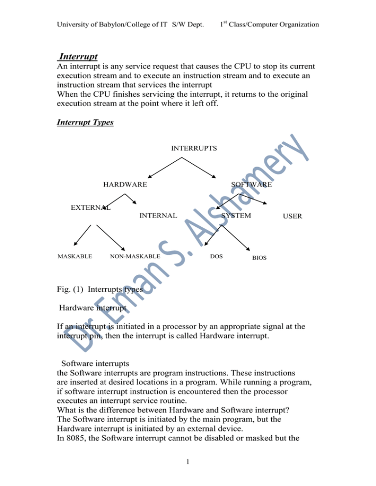
1st Class/Computer Organization University of Babylon/College of IT S/W Dept. Interrupt An interrupt is any service request that causes the CPU to stop its current execution stream and to execute an instruction stream and to execute an instruction stream that services the interrupt When the CPU finishes servicing the interrupt, it returns to the original execution stream at the point where it left off. Interrupt Types INTERRUPTS HARDWARE SOFTWARE EXTERNAL INTERNAL MASKABLE SYSTEM NON-MASKABLE DOS USER BIOS Fig. (1) Interrupts types Hardware interrupt If an interrupt is initiated in a processor by an appropriate signal at the interrupt pin, then the interrupt is called Hardware interrupt. Software interrupts the Software interrupts are program instructions. These instructions are inserted at desired locations in a program. While running a program, if software interrupt instruction is encountered then the processor executes an interrupt service routine. What is the difference between Hardware and Software interrupt? The Software interrupt is initiated by the main program, but the Hardware interrupt is initiated by an external device. In 8085, the Software interrupt cannot be disabled or masked but the 1 University of Babylon/College of IT S/W Dept. 1st Class/Computer Organization Hardware interrupt except TRAP can be disabled or masked Interrupts provide a mechanism of transferring control from a foreground process (the current executing program) to an Interrupt Service Routine. When such a transfer is initiated by the hardware in response to special internal or external conditions, a hardware interrupt is said to have occurred. External hardware interrupts are generated by peripheral devices and are the main mechanism used by these devices to get the attention of the processor. Certain external hardware interrupts are maskable in that they may be disabled by clearing the Interrupt enable flag (IF) in the flags register. External hardware interrupts that cannot be disabled by clearing IF are called non-maskable interrupts. Typically, non-maskable interrupts are hardware events that must be responded to immediately by the CPU. An example of such an event is the occurrence of a memory or I/O parity error. Internal hardware interrupts are hardware interrupts that are generated internally to the processor, generally on the occurrence of an error condition. A software interrupt occurs when an INT instruction is executed. With a software interrupt, the type of the interrupt is specified in the INT instruction. With hardware interrupts, the type of the interrupt is supplied by the interrupting hardware. In both cases, when an interrupt occurs, the addresses specified in the related interrupt vector are used to set the CS and IP registers with the starting segment : offset address of the associated interrupt service routine. It is this routine which performs whatever functions necessary is servicing the interrupt. The same sequence of events as was explained for the mechanism of the INT instruction, happens in the case of hardware interrupts.There are 256 possible interrupt types available on the IBM PC with certain of these reserved for various system purposes, and certain available for userdefined interrupt service routines. External Interrupts The external interrupt facility is used in the IBM PC to alert the processor that a peripheral device requires the CPU’s attention. The 8086/8088 microprocessor has two control lines that can signal interrupts. The lines are designated as INTR (Interrupt Request) and NMI (Non-maskable Interrupt). Maskable interrupts use the INTR signal line, and nonmaskable interrupts use the NMI signal line. In the 8086 microprocessor ,there are two main types of interrupt, internal and external hardware interrupts. Hardware interrupts occur when a peripheral device asserts an interrupt input pin of the microprocessor. Whereas internal interrupts are initiated by the state of the CPU (e.g. divide by zero error) or by an instruction. Provided the interrupt is permitted, it will be acknowledged by the processor at the end of the current memory cycle. The processor then 2 University of Babylon/College of IT S/W Dept. 1st Class/Computer Organization services the interrupt by branching to a special service routine written to handle that particular interrupt. Upon servicing the device, the processor is then instructed to continue with what is was doing previously by use of the "return from interrupt" instruction. The status of the programme being executed must first be saved. The processors registers will be saved on the stack, or, at very least, the programme counter will be saved. Preserving those registers which are not saved will be the responsibility of the interrupt service routine. Once the programme counter has been saved, the processor will branch to the address of the service routine. Interrupt driven I/O: Memory mapped I/O • I/O devices and the memory share the same address space, the arrangement is called Memory-mapped I/O. • In Memory-mapped I/O portions of address space are assigned to I/O devices and reads and writes to those addresses are interpreted as commands to the I/O device. “DATAIN” is the address of the input buffer associated with the keyboard. - Move DATAIN, R0 reads the data from DATAIN and stores them into processor register R0; - Move R0, DATAOUT sends the contents of register R0 to location DATAOUT Option of special I/O address space or incorporate as a part of memory address space (address bus is same always). When the processor places the address and data on the memory bus, the memory system ignores the operation because the address indicates a portion of the memory space used for I/O. The device controller, however, sees the operation, records the data, and transmits it to the device as a command. Memory mapped I/O can also be used to transmit data by writing or reading to select addresses. The device uses the address to determine the type of command, and the data may be provided by a write or obtained by a read. A program request usually requires several separate I/O operations. Furthermore, the processor may have to interrogate the status of the device between individual commands to determine whether the command completed successfully. 3 University of Babylon/College of IT S/W Dept. 1st Class/Computer Organization Registers: DATAIN, DATAOUT, STATUS, CONTROL Flags: SIN, SOUT - Provides status information for keyboard and display unit KIRQ, DIRQ – Keyboard, Display Interrupt request bits DEN, KEN –Keyboard, Display Enable bits. The process of periodically checking status bits to see if it is time for the next I/O operation, is called polling. Polling is the simplest way for an I/O device to communicate with the processor. The I/O device simply puts the information in a Status register, and the processor must come and get the information. The processor is totally in control and does all the work. The disadvantage of polling is that it can waste a lot of processor time because processors are so much faster than I/O devices. The processor may read the Status register many times, only to find that the device has not yet completed a comparatively slow I/O operation, or that the mouse has not budged since the last time it was polled. When the device completes an operation, we must still read the status to determine whether it (I/O) was successful. Overhead in a polling interface lead to the invention of interrupts to notify the processor when an I/O device requires attention from the processor. Vectored Interrupts • Device requesting an interrupt identifies itself directly to the processor • The device sends a special code to the processor over the bus. • The code contains the – identification of the device, – starting address for the ISR, – address of the branch to the ISR 4 University of Babylon/College of IT S/W Dept. 1st Class/Computer Organization • PC finds the ISR address from the code. Interrupt-driven I/O, employs I/O interrupts to indicate to the processor that an I/O device needs attention. When a device wants to notify the processor that it has completed some operation or needs attention, it causes the processor to be interrupted. When I/O Device is ready, it sends the INTERRUPT signal to processor via a dedicated controller line • Using interrupt we are ideally eliminating WAIT period • In response to the interrupt, the processor executes the Interrupt Service Routine (ISR) • All the registers, flags, program counter values are saved by the processor before running ISR • The time required to save status & restore contribute to execution overhead “Interrupt Latency” interrupt-acknowledge signal - I/O device interface accomplishes this by execution of an instruction in the interrupt-service routine (ISR) that accesses a status or data register in the device interface; implicitly informs the device that its interrupt request has been recognized. IRQ signal is then removed by device. ISR is a sub-routine – may belong to a different user than the one being executed and then halted. The condition code flags and the contents of any registers used by both the interrupted program and the interrupt-service routine are saved and restored. The sequence of events involved in handling an interrupt request from a single device.Assuming that interrupts are enabled, the following is a typical scenario: 1. The device raises an interrupt request. 2. The processor interrupts the program currently being executed at the time 3. Interrupts are disabled by changing the control bits in the PS. 4. The device is informed that its request has been recognized, and in response, it deactivates the interrupt request signal. 5. The action requested by the interrupt is performed by the interruptservice routine. 6. Interrupts are enabled and 7-execution of the interrupted program is resumed. 5 University of Babylon/College of IT S/W Dept. 1st Class/Computer Organization Handling Multiple Devices 1-Interrupt Nesting Organizing I/O devices in a prioritized structure. • Each of the interrupt-request lines is assigned a different priority level. • The processor is interrupted only by a high priority device. Daisy Chaining • The interrupt request line INTR is common to all the devices • The interrupt acknowledgement line INTA is connected to devices in a DAISY CHAIN way • INTA propagates serially through the devices • Device that is electrically closest to the processor gets high priority Daisy Chaining with Priority Group • Combining Daisy chaining and Interrupt nesting to form priority group • Each group has different priority levels and within each group devices are connected in daisy chain way 6 University of Babylon/College of IT S/W Dept. 7 1st Class/Computer Organization


