Determination of Pin Determination of Pin--bearing Strength for bearing Strength for
advertisement

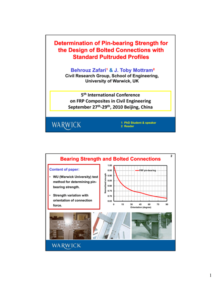
Determination of PinPin-bearing Strength for the Design of Bolted Connections with Standard Pultruded Profiles Behrouz Zafari¹ & J. Toby Mottram² Civil Research Group, School of Engineering, University of Warwick, UK 5th International Conference on FRP Composites in Civil Engineering FRP C it i Ci il E i i th th September 27 ‐29 , 2010 Beijing, China 1 PhD Student & speaker 2 Reader 2 Bearing Strength and Bolted Connections 1.00 Content of paper: method for determining pinb i strength. bearing t th • Strength variation with orientation of connection force. Normalised strength • WU (Warwick University) test FRP pin-bearing 0.95 0.90 0.85 0 80 0.80 0.75 0.70 0.65 0 15 30 45 60 Orientation (degree) 75 90 1 3 Types of Bolted Connections and Joints Design of frame joints, such as the web cleated type shown on top-right web-cleated top right (classify as simple using the principles in BS EN 1993-1-8:2006), with the design of plate-to-plate connections, such as there is in each of the cleat legs and bracing members (bottom-right). 4 Plate--to Plate to--plate Resistances Distinct modes of failure (single-bolted connections) or e1 dn 2e2 (a) (b) (c) (d) (a) bearing, (b) net-tension, (c) shear-out, (d) cleavage 2 Strength formula – Bearing mode of failure Rbr t d Fbr 5 Compression load t is thickness of FRP d is diameter of bolt Fbr is pin-bearing strength for the orientation of material to the resultant connection force. = 0° (or longitudinal) when direction of pultrusion is aligned with connection force. WU pin-bearing strength test rig and 100x 100 mm specimen size Strength formula – Bearing mode of failure Specimens from web of 203 × 203 × 9.53 mm Wide Flange section Creative Pultrusions Inc. section. Inc Pultex 1525 series with a thermoset polyester resin. 6 Bearing failure - 0o specimen Test results for 0°, 45° and 90˚ material orientations, at room temperature. 3 7 Pin--bearing Strength test results Pin Longitudinal web material,F br Mean web thickness, t (mm) 9.16 9.14 9.12 9.14 Mean notch diameter, dn (mm) 11.8 14.8 20.9 27.9 Mean pin diameter, d (mm) 9.7 12.2 18.8 25.4 Mean clearance, dn - d (mm) 1.9 2.6 2.1 2.5 No. of nominally identical specimens 11 11 11 11 136 Mean pin-bearing strength, (N/mm2) 188 170 154 SD (N/mm2) 6.2 9.1 12.7 14.8 CV (%) 3.3 5.3 8.4 10.9 Characteristic value* (N/mm2) 177 155 133 111 Mean d/t ratio 1.06 1.34 2.05 2.78 di ti direction 90o 0o Note: * Characteristic value = Mean – 1.72SD (Batches of 10) Pin--bearing Strength Test Results Pin 8 200 Transverse (90o) direction Pin-bearing stress (N/mm m2) 175 • Load-stroke curves are virtually linear for stroke to 0.8 mm. 150 125 • For hole diameters of 12 and 15 mm there is a higher load after initial failure. 100 75 Hole diameter (mm) 50 12 15 25 21 28 • For hole diameter 21 and 28 mm the bearing failure is brittle. 0 0.0 0.5 1.0 1.5 2.0 2.5 Stroke (mm) 4 9 Pin--bearing Strength Test Results Pin 200 For nominal hole diameter of 28 mm (d/t = 2.78) Pin-bearing stress (N/m mm2) 175 150 Fbr / Fbr 125 0° 100 45º modulus of elasticity 45° 90° 75 = 1.13 is 11.2 kN/mm2 ; 1.12 higher than in the 50 90o direction. 25 Two ratios the same. 0 0.0 0.5 1.0 1.5 Stroke (mm) 2.0 2.5 Pin--bearing Strength Test Results Pin 10 Characteristic pin bearring strength (N/mm2) 200 175 Hole clearance is 1.9 mm or larger 150 0° 45° 125 90° 100 75 50 25 0 1 1.5 d/t 2 2.5 3 (Ratio of pin diameter-to-material thickness) Reduces between 50 and 60% on increasing pin diameter from 9.7 to 25.4 mm. 5 11 Concluding Remarks • Warwick University pin-bearing strength test method has the potential to be developed into a standard test method. • Minimum characteristic strength values are 111 N/mm2 (0o) (CV @ 11%), 2 (45o) (CV @ 4%) 2 (90o) (CV @ 6 111 N/mm N/ 4%), and d 97 N/mm N/ 6.6%). 6%) • Characteristic strengths are very different (and unsafe) from 206 N/mm2 for 0o, and 124 N/mm2 for 90o given in Creative Pultrusions’ design manual. • Pin-bearing strength reduces with increase in the ratio of the pin diameterto-material thickness and standard test methods do not account for this. • Further series of tests are required to establish design strengths for conditions found in practice over the life of pultruded structures. 5th International Conference on Advanced Composites p in Construction (ACIC 2011) University of Warwick 6 - 8th September 2011 www.acic-conference.com Email: B.Zafari@warwick.ac.uk 2010 6

