A regenerative gas turbine with intercooling and reheat operates at
advertisement
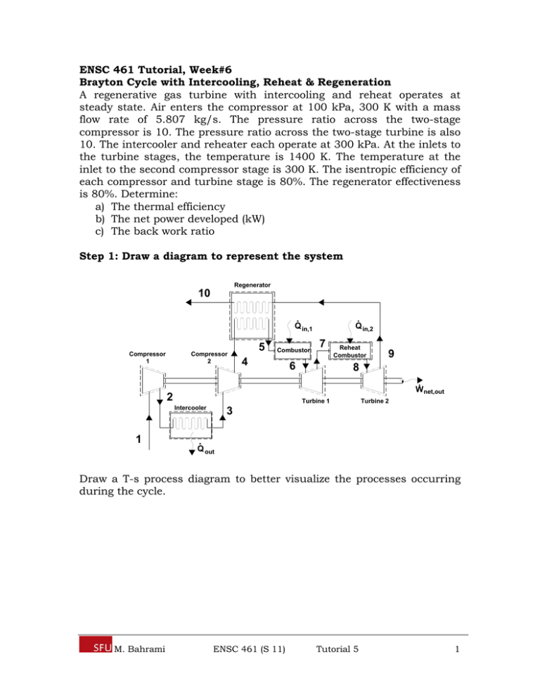
ENSC 461 Tutorial, Week#6 Brayton Cycle with Intercooling, Reheat & Regeneration A regenerative gas turbine with intercooling and reheat operates at steady state. Air enters the compressor at 100 kPa, 300 K with a mass flow rate of 5.807 kg/s. The pressure ratio across the two-stage compressor is 10. The pressure ratio across the two-stage turbine is also 10. The intercooler and reheater each operate at 300 kPa. At the inlets to the turbine stages, the temperature is 1400 K. The temperature at the inlet to the second compressor stage is 300 K. The isentropic efficiency of each compressor and turbine stage is 80%. The regenerator effectiveness is 80%. Determine: a) The thermal efficiency b) The net power developed (kW) c) The back work ratio Step 1: Draw a diagram to represent the system Regenerator 10 Q in,1 Compressor 1 Compressor 2 5 Combustor 4 Q in,2 7 6 Reheat Combustor 9 8 Wnet,out 2 Turbine 1 Intercooler Turbine 2 3 1 Q out Draw a T-s process diagram to better visualize the processes occurring during the cycle. M. Bahrami ENSC 461 (S 11) Tutorial 5 1 T 6 8 5 7 9 7s 4s 9s 4 10 2 2s 3 1 s Step 2: Write out what is required to solve for a) The thermal efficiency b) The net power developed (kW) c) The back work ratio Step 3: Prepare a property table 1 2 2s 3 4 4s 5 6 7 7s 8 9 9s 10 T(K) 300 P(kPa) 100 300 300 300 1000 1000 1000 1000 300 300 300 100 100 100 300 1400 1400 Step 4: State your assumptions Assumptions: 1) ke, pe 0 2) cold-air-standard assumptions are applicable 3) SSSF M. Bahrami ENSC 461 (S 11) Tutorial 5 2 Step 5: Solve Part a) The thermal efficiency (benefit/cost) of the system can be expressed as the ratio of the system’s net work output to the system’s heat input (there are heat inputs at the combustor AND the reheat combustor) as shown in Eq1. Note: the heat input that occurs from location 4 to 5 is an internal energy transfer, getting its energy from location 9 to 10 and thus does not qualify as a heat input into the system. th wnet ,out (Eq1) qin ,1 qin , 2 The wnet,out can be determined from the difference between the work output of the turbines and the work input to the compressors. The work for each of these devices can be determined from energy balances applied to the individual control volumes to obtain Eq2. Note: The assumptions of steady operating conditions ke & pe 0 have been applied in each of the energy balances. wnet ,out wt ,1 wt , 2 wc ,1 wc , 2 wnet ,out (h6 h7 ) (h8 h9 ) (h2 h1 ) (h4 h3 ) (Eq2) Since air is the working fluid, modeled as an ideal gas with constant specific heats at room temperature, Eq2 can be rewritten by applying the ideal gas relation for the enthalpy difference between two states [e.g. h2 h1 = cp(T2-T1)], as shown in Eq3. wnet ,out c p [(T6 T7 ) (T8 T9 )] [(T2 T1 ) (T4 T3 )] (Eq3) The heat input can be determined from energy balances applied to the individual control volumes (combustor and reheat combustor), similar to what was done in Eq2 and Eq3, to obtain Eq4. qin ,1 qin , 2 (h6 h5 ) (h8 h7 ) c p [(T6 T5 ) (T8 T7 )] (Eq4) From Eq3 and Eq4 it is observed that the temperatures for locations 1 through 9 must be known in order to determine the thermal efficiency. Location 1 T1 = 300 K (Given compressor 1 inlet conditions) M. Bahrami ENSC 461 (S 11) Tutorial 5 3 Location 2 The definition of the isentropic efficiency of the compressor can be used to determine the temperature at Location 2 as shown in Eq5. c h2 s h1 c p (T2 s T1 ) T T1 T2 T1 2 s h2 h1 c p (T2 T1 ) c (Eq5) To find the temperature at Location 2 from Eq5, the temperature at Location 2 if the compression process were isentropic must first be determined. The ideal gas relations for isentropic processes can be used to find the temperature at state 2s as shown below. T2 s P2 T1 P1 k 1 k 0.4 300[kPa] 1.4 410.62[ K ] T2 s 300K 100[kPa] Substituting this back into Eq5, the actual temperature at Location 2 can be solved for as shown below. T2 T1 T2 s T1 c 300[ K ] 410.62[ K ] 300[ K ] 438.3[ K ] 0.80 Location 3 T3 = 300 K (Given compressor 2 inlet conditions) Location 4 A similar analysis to what was used to determine the temperature at Location 2 can be used to determine the temperature at Location 4. The isentropic efficiency of the compressor can again be used to determine the temperature at Location 4, as shown in Eq6. c h4 s h3 c p (T4 s T3 ) T T3 T4 T3 4 s h4 h3 c p (T4 T3 ) c (Eq6) To find the temperature at Location 4 from Eq6, the temperature at Location 4 if the compression process were isentropic must first be determined. The ideal gas relations for isentropic processes can be used to find the temperature at state 4s as shown below. T4 s P4 T3 P3 M. Bahrami k 1 k 0.4 1000[kPa] 1.4 423.17[ K ] T4 s 300K 300[kPa] ENSC 461 (S 11) Tutorial 5 4 Substituting this result into Eq6, the temperature at location 4 can be determined as shown below. T4 T3 T4 s T3 c 300[ K ] 423.2[ K ] 300[ K ] 453.96[ K ] 0.80 Location 5 To find the temperature at Location 5 we can make use of the regenerator’s effectiveness, as shown in Eq7. regen q regen,act q regen,max h5 h4 c p (T5 T4 ) T5 T4 regen (T9 T4 ) h9 h4 c p (T9 T4 ) (Eq7) At this point the temperature at Location 9 is still unknown. Once T9 has been determined Eq7 can be used to solve for T5. Location 6 T6 = 1400 K (Given turbine 1 inlet conditions) Location 7 The definition for the isentropic efficiency of a turbine can be used to determine the temperature at Location 7, as shown in Eq8. t c p (T6 T7 ) h6 h7 T7 T6 t (T6 T7 s ) h6 h7 s c p (T6 T7 s ) (Eq8) To find the temperature at Location 7 from Eq8 the temperature at Location 7 if the expansion process were isentropic must first be determined. The ideal gas relation for isentropic processes can be used to find the temperature at state 7s as shown below. T7 s P7 T6 P6 k 1 k 0.4 300[kPa] 1.4 992.51[ K ] T7 s 1400K 1000[kPa] Substituting this result into Eq8 the temperature at Location 7 can be determined as shown below. T7 T6 t (T6 T7 s ) 1400[ K ] (0.8)(1400[ K ] 992.51[ K ]) 1074[ K ] M. Bahrami ENSC 461 (S 11) Tutorial 5 5 Location 8 T8 = 1400 K (Given turbine 2 inlet conditions) Location 9 The definition for the isentropic efficiency of a turbine can be used to determine the temperature at Location 9, as shown in Eq9. t c p (T8 T9 ) h8 h9 T9 T8 t (T8 T9 s ) h8 h9 s c p (T8 T9 s ) (Eq9) To find the temperature at Location 9 from Eq9 the temperature at Location 9 if the expansion process were isentropic must first be determined. The ideal gas relation for isentropic processes can be used to find the temperature at state 9s as shown below. T9 s P9 T8 P8 k 1 k 0.4 100[kPa] 1.4 1023[ K ] T9 s 1400K 300[kPa] Substituting this result into Eq9 the temperature at Location 9 can be determined as shown below. T9 T8 t (T8 T9 s ) 1400[ K ] (0.8)(1400[ K ] 1023[ K ]) 1098.3[ K ] Location 5 cont’d The temperature at Location 5 can now be solved using Eq7 as shown below. T5 T4 regen (T9 T4 ) 453.96 (0.8)(1098.3 453.96) 969.43[ K ] M. Bahrami ENSC 461 (S 11) Tutorial 5 6 The property table is now complete and the thermal efficiency can be determined. T(K) 300 438.3 410.62 300 453.96 423.2 969.43 1400 1074 992.51 1400 1098.3 1023 1 2 2s 3 4 4s 5 6 7 7s 8 9 9s 10 P(kPa) 100 300 300 300 1000 1000 1000 1000 300 300 300 100 100 100 Substituting Eq3 and Eq4 into Eq1, the thermal efficiency can be determined as shown below. th (T6 T7 ) (T8 T9 ) (T2 T1 ) (T4 T3 ) (T6 T5 ) (T8 T7 ) th (1400 1074) (1400 1098.3)[ K ] (438.3 300) (453.96 300)[ K ] (1400 969.43)[ K ] (1400 1074)[ K ] 326 301.7 [ K ] 138.3 153.96[ K ] th 430.57 326K th Answer a) 627.7 292.26 44.3% 756.57 Part b) The net power developed will be the wnet,out (Eq3) multiplied by the mass flow rate of air. The mass flow rate of air is given in the problem statement as 5.807 kg/s. M. Bahrami ENSC 461 (S 11) Tutorial 5 7 kJ W net ,out m air wnet ,out (5.807[kg / s ])1.005 627.7[ K ] 292.26K kg K Answer b) W net ,out 1957.6[kW ] Part c) The back work ratio is defined as the ratio of compressor work to the turbine work. bwr wc ,in wt ,out Answer c) 292.26 46.6% 627.7 Step 6: Concluding Remarks & Discussion a) The thermal efficiency was calculated as 0.443. b) The net power developed is 1957.6 kW. c) The back work ratio is 0.466. M. Bahrami ENSC 461 (S 11) Tutorial 5 8
