ENSC 388 Week #9, Tutorial #7 – Steady State Conduction
advertisement
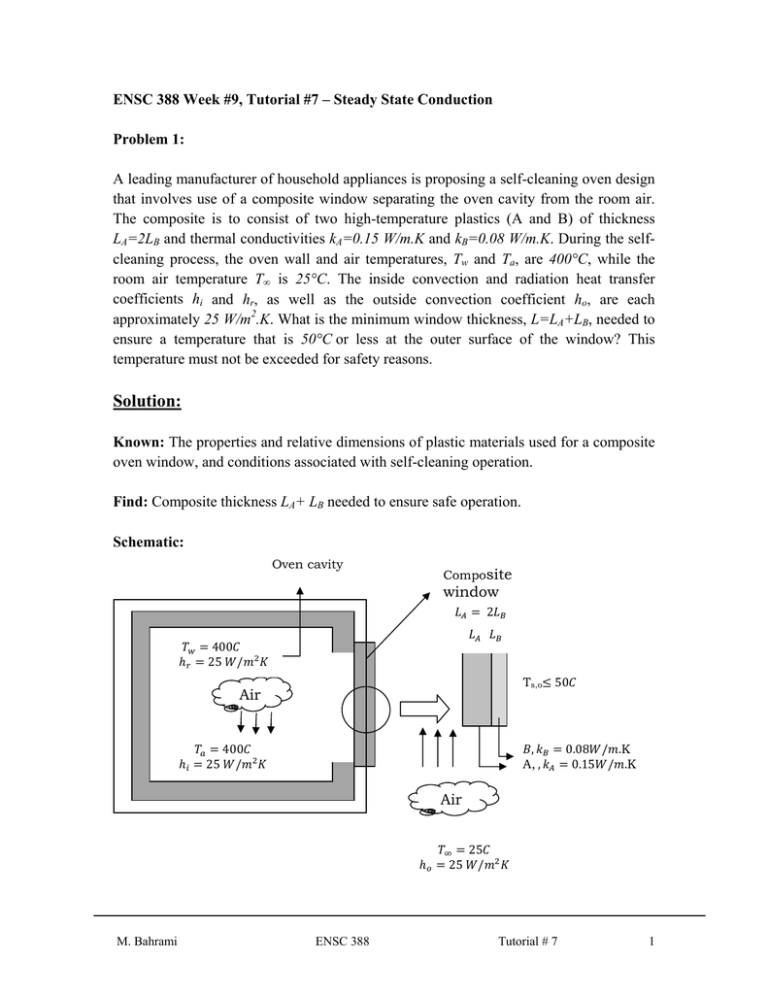
ENSC 388 Week #9, Tutorial #7 – Steady State Conduction Problem 1: A leading manufacturer of household appliances is proposing a self-cleaning oven design that involves use of a composite window separating the oven cavity from the room air. The composite is to consist of two high-temperature plastics (A and B) of thickness LA=2LB and thermal conductivities kA=0.15 W/m.K and kB=0.08 W/m.K. During the selfcleaning process, the oven wall and air temperatures, Tw and Ta, are 400°C, while the room air temperature T∞ is 25°C. The inside convection and radiation heat transfer coefficients hi and hr, as well as the outside convection coefficient ho, are each approximately 25 W/m2.K. What is the minimum window thickness, L=LA+LB, needed to ensure a temperature that is 50°C or less at the outer surface of the window? This temperature must not be exceeded for safety reasons. Solution: Known: The properties and relative dimensions of plastic materials used for a composite oven window, and conditions associated with self-cleaning operation. Find: Composite thickness LA+ LB needed to ensure safe operation. Schematic: Oven cavity Composite window 2 400 25 / Ts,o Air 25 50 , A, , 400 / 0.08 / .K 0.15 / .K Air 25 M. Bahrami ENSC 388 25 / Tutorial # 7 1 Assumptions: 1. 2. 3. 4. Steady-state conditions exist. Conduction through the window is one-dimensional. Contact resistance is negligible. Radiation absorption within the window is negligible; hence no internal heat generation (radiation exchange between window and oven walls occurs at the window inner surface). 5. Radiation exchange between window outer surface and surroundings is negligible. 6. Each plastic is homogeneous with constant properties. Analysis: The thermal circuit can be constructed by recognizing that resistance to heat flow is associated with convection at the outer surface, conduction in the plastics, and convection and radiation at the inner surface. Accordingly, the circuit and the resistances are of the following form: 1 1 , , 1 Since the outer surface temperature of the window, Ts,o, is prescribed, the required window thickness may be obtained by applying an energy balance at this surface. That is, from the following equation Eq. (1) for with Tw=Ta, we have , Eq. (2) ∑ and from the Newton’s cooling law, M. Bahrami ENSC 388 Tutorial # 7 2 , Eq. (3) ∞ The total thermal resistance between the oven cavity and the outer surface of the window includes an effective resistance associated with convection and radiation, which act in parallel at the inner surface of the window, and the conduction resistances of the window materials. Hence 1 1 1 1 Eq. (4) or 1 1 Eq. (5) Substituting into the energy balance, it follows that , , Eq. (6) ∞ 2 Hence, solving for LA, 1 , / , 1 0.04 400 50 50 25 1/0.15 1/0.16 . ∞ 1 2 0.02 . . / 0.0418 Since LB = LA/2 =0.0209 m, L= LA+LB = 0.0627 m = 62.7 mm Comments: 1. The self-cleaning operation is a transient process, as far as the thermal response of the window is concerned, and steady-state conditions may not be reached in the M. Bahrami ENSC 388 Tutorial # 7 3 time required for cleaning. However, the steady-state condition provides the maximum possible value of Ts,o and hence is well suited for the design calculation. 2. Radiation exchange between the oven walls and the composite window actually depends on the inner surface temperature Ts,i, and although it has been neglected, there is radiation exchange between the window and the surroundings, which depends on Ts,o. A more complete analysis may be made to concurrently determine Ts,i and Ts,o. Approximating the oven cavity as a large enclosure relative to the window and applying an energy balance at the inner surface, it follows that " , " " , Eq. (7) or , , , , Eq. (8) , / / Approximating the kitchen walls as a large isothermal enclosure relative to the window, with Tw,o=T∞ and this time applying an energy balance at the outer surface, it follows that " " " , Eq. (9) , or , / , / , , , ∞ Eq. (10) If all other quantities are known, Eq. (8) and Eq. (10) may be solved for Ts,i and Ts,o. Problem 2: The engine cylinder of a motorcycle is constructed of 2024-T6 aluminum alloy and is of height H = 0.15 m and outside diameter D = 50 mm. Under typical operating conditions the outer surface of the cylinder is at a temperature of 500 K and is exposed to ambient air at 300 K, with a convection coefficient of 50 W/m2. K. Annular fins are integrally cast with the cylinder to increase heat transfer to the surroundings. Consider five such fins, M. Bahrami ENSC 388 Tutorial # 7 4 which are of thickness t = 6 mm, length L = 20 mm, and equally spaced. What is the increase in heat transfer due to use of the fins? Solution Known : Operating conditions of a finned motorcycle cylinder. Find: Increase in heat transfer associated with using fins. Schematic: Engine cylinder cross section (2024 T6 Al alloy) S Tb=500 K 0.15 50 300 / 6 Air r1 r2 25 20 45 Assumptions: 1. Steady-state conditions. 2. One-dimensional radial conduction in fins. 3. Constant properties. 4. Negligible radiation exchange with surroundings. 5. Uniform convection coefficient over outer surface (with or without fins). Properties: Table A-24E, 2024-T6 aluminum (T = 400 K): k = 186 W/m. K. Analysis: With the fins in place, the heat transfer rate is given by the following equation M. Bahrami ENSC 388 Tutorial # 7 5 1 Eq. (1) 1 where = 2π 2 [(0.048m)2 - (0.025 m)2] = 0.0105 m2 and, also the total area of the finned surface is Eq. (2) therefore, we find At = NAf 2πr1(H - Nt) = 0.0527 m2 + 2π(0.025 m) [0.15 m - 0.03 m] = 0.0716 m2. With reference to Fig. 10-43 in Cengel book, r2c/r1 = 1.92, Lc = 0.023 m, Ap = 1.380 × 10- 4 m2, we obtain / 0.15 0.95. With the fins, the total heat Hence, from Figure 10-43, the fin efficiency is transfer rate is then 0.0527 m2 = 50 W/m2. K × 0.0716 m2 [1 × (0.05)] 200 K = 690 W 0.0716 m2 Without the fins, the convection heat transfer rate would be , = h(2πr1H) b = 50 W/m2.K(2π× 0.025 m × 0.15 m)200 K = 236 W Hence Δ , 454 W Comments: Although the fins significantly increase heat transfer from the cylinder, considerable improvement could still be obtained by increasing the number of fins. We assess this possibility by computing , as a function of N, first by fixing the fin thickness at t = 6 mm and increasing the number of fins by reducing the spacing between fins. Prescribing a fin clearance of 2 mm at each end of the array and a minimum fin gap of 4 mm. the maximum allowable number of fins is N = H/S =0.15 m/(0.004 + 0.006) m = 15. The parametric calculations yield the following variation of qt with N: M. Bahrami ENSC 388 Tutorial # 7 6 Number of fins, N The number of fins could also be increased by reducing the fin thickness. If the fin gap is fixed at (S - t) = 4 mm and manufacturing constraints dictate a minimum allowable fin thickness of 2 mm, up to N = 25 fins may be accommodated. In this case the parametric calculations yield Number of fins, N The foregoing calculations are based on the assumption that h is not affected by a reduction in the fin gap. The assumption is reasonable as long as there is no interaction between boundary layers that develop on the opposing surfaces of adjoining fins. Note 2 r1(H - Nt) for the prescribed conditions, qt increases linearly with that, since NAf increasing N. M. Bahrami ENSC 388 Tutorial # 7 7
