Integral Relations for a Control Volume
advertisement

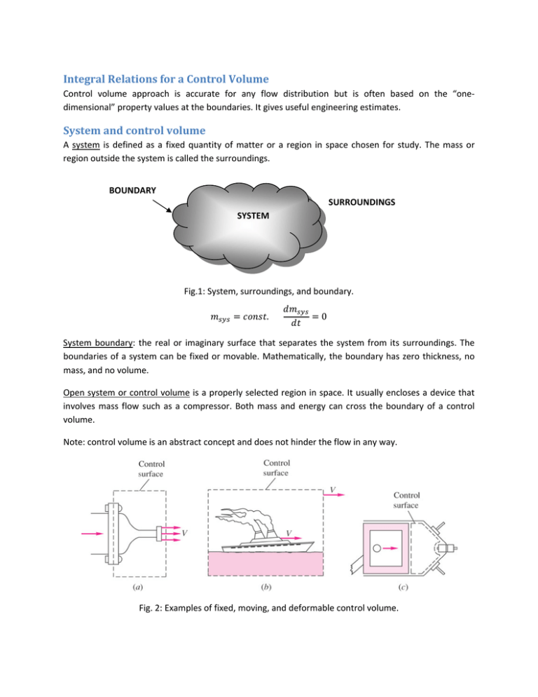
Integral Relations for a Control Volume Control volume approach is accurate for any flow distribution but is often based on the “one‐ dimensional” property values at the boundaries. It gives useful engineering estimates. System and control volume A system is defined as a fixed quantity of matter or a region in space chosen for study. The mass or region outside the system is called the surroundings. BOUNDARY SURROUNDINGS SYSTEM Fig.1: System, surroundings, and boundary. . 0 System boundary: the real or imaginary surface that separates the system from its surroundings. The boundaries of a system can be fixed or movable. Mathematically, the boundary has zero thickness, no mass, and no volume. Open system or control volume is a properly selected region in space. It usually encloses a device that involves mass flow such as a compressor. Both mass and energy can cross the boundary of a control volume. Note: control volume is an abstract concept and does not hinder the flow in any way. Fig. 2: Examples of fixed, moving, and deformable control volume. Volume and mass flow rate Fig.3: Volume flow rate through arbitrary surface. Let n be defined as the unit vector normal to dA. Then the amount of fluid swept through dA in time dt is: . The integral of dV/dt is the total volume rate of flow Q through the surface S: . where Vn is the normal component of the velocity. We consider n to be the outward normal unit vector. Volume can be multiplied by density to obtain the mass flow . . If density and velocity are constant over the surface S, a simple expression results: The Reynolds Transport Theorem To convert a system analysis to control volume analysis, we must convert our mathematics to apply to a specific region rather than to individual masses. This conversion is called the Reynolds transport theorem. Consider a fixed control volume with an arbitrary flow pattern through. In general, each differential area dA of surface will have a different velocity V with a different angle θ with the normal to dA. One can find: M. Bahrami Fluid Mechanics (S 09) Integral Relations for CV 2 In flow volume: Outflow volume . Fig. 4: Control volume, Reynolds transport theorem. Let B be any property of the fluid (energy, momentum, enthalpy, etc.) and value of the amount B per unit mass in any small element of the fluid. ⁄ be the intensive The total amount of B in the control volume is: A change within the control volume: Outflow of β from the control volume: Inflow of β to the control volume: CV and CS refer to control volume and control surface, respectively. For the system shown in Fig. 4, the instantaneous change of B in the system is sum of the change within, plus the outflow, minus the inflow: M. Bahrami Fluid Mechanics (S 09) Integral Relations for CV 3 Note the control volume is fixed in space, the elemental volume do not vary with time. Also we note that V cosθ is the component of V normal to the area element of the control surface. Thus we can write: The vector form of the above equation is: . And the Reynolds transport theorem, in the vector form, becomes: . One­dimensional flux term approximation In many situations, the flow crosses the boundaries of the control surface at simplified inlets and exits that are approximately one‐dimensional (the velocity can be considered uniform across each control surface). For a fixed control volume, the surface integral reduces to: | | Example 1 A fixed control volume has three one‐dimensional boundary sections, as shown in the figure below. The flow within the control volume is steady. The flow properties at each section are tabulated below. Find the rate of change of energy that occupies the control volume at this instant. Control surface 1 2 3 M. Bahrami type inlet inlet outlet , kg/m3 800 800 800 V, m/s 5.0 8.0 17.0 Fluid Mechanics (S 09) A, m2 2.0 3.0 2.0 e, J/kg 300 100 150 Integral Relations for CV 4 Conservation of mass For conservation of mass, B=m and ⁄ 1. The Reynolds transport equation becomes: . If the control volume only has a number of one‐dimensional inlets and outlets, we can write: 0 Note: for steady‐state flow, ⁄ 0, and the conservation of mass becomes: This means, in steady flow, the mass flows entering and leaving the control volume must balance. Average velocity In cases that fluid velocity varies across a control surface, it is often convenient to define an average velocity. 1 . The average velocity is only a concept, i.e., when it is multiplied by the area gives the volume flow. If the density varies across the cross‐section, we similarly can define an average density: 1 M. Bahrami Fluid Mechanics (S 09) Integral Relations for CV 5 Example 2 In a grinding and polishing operation, water at 300 K is supplied at a flow rate of 4.264×10‐3 kg/s through a long, straight tube having an inside diameter of D=2R=6.35 mm. Assuming the flow within the tube is laminar and exhibits a parabolic velocity profile: 1 where umax is the maximum fluid velocity at the center of the tube. Using the definition of the mass flow rate and the concept of average velocity, show that: u(r) uavg R r r L R The linear momentum equation For Newton’s second law, the property being differentiated is the linear momentum, mV. Thus B =mV ⁄ and . The Reynolds transport theorem becomes: . Note that this is a vector equation and has three components. Momentum flux term, . If cross‐section is one‐dimensional, V and are uniform and over the area, momentum flux simplifies: For one‐dimensional inlets and outlets, we have: ∑ Net pressure force on a closed CV Recall that the external pressure force on a surface is normal and inward. M. Bahrami Fluid Mechanics (S 09) Integral Relations for CV 6 Since the unit vector n is outward, we can write: If the pressure has a uniform value pa all around the surface, the net pressure force is zero. 0 This is independent of the shape of the surface. Thus pressure force problems can be simplified by subtracting any convenient uniform pressure pa and working only with the pieces of gage pressure that remain: Note: The axial velocity is non‐uniform, thus the simple momentum flux calculation . is not accurate. To consider the effects of non‐uniform velocity, we introduce a correction factor β. or Values of β can be calculated using the duct velocity profile and the above definition: Laminar flow: Turbulent flow: M. Bahrami 1 1 4/3 Fluid Mechanics (S 09) Integral Relations for CV 7


