For ConTech Lighting 6" LED Recessed Downlight Series: RA6LNC INSTALLATION PROCEDURES
advertisement
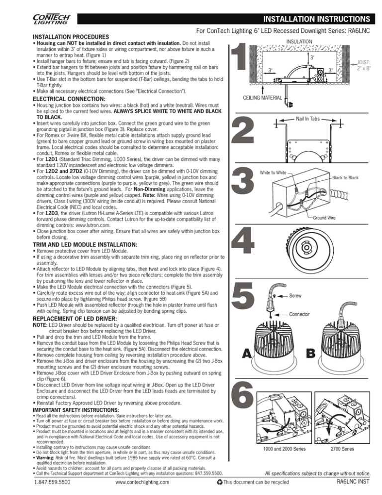
For ConTech Lighting 6" LED Recessed Downlight Series: RA6LNC INSTALLATION PROCEDURES INSULATION • Housing can NOT be installed in direct contact with insulation. Do not install insulation within 3" of fixture sides or wiring compartment, nor above fixture in such a manner to entrap heat. (Figure 1) • Install hanger bars to fixture; ensure end tab is facing outward. (Figure 2) • Extend bar hangers to fit between joists and position fixture by hammering nail on bars into the joists. Hangers should be level with bottom of the joists. • Use T-Bar slot in the bottom bars for suspended (T-Bar) ceilings, bending the tabs to hold T-Bar tightly. • Make all necessary electrical connections (See “Electrical Connection”). 3" 3" JOIST: 2" x 8" 3" CEILING MATERIAL ELECTRICAL CONNECTION: • Housing junction box contains two wires: a black (hot) and a white (neutral). Wires must be spliced to the current feed wires. ALWAYS SPLICE WHITE TO WHITE AND BLACK TO BLACK. • Insert wires carefully into junction box. Connect the green ground wire to the green grounding pigtail in junction box (Figure 3). Replace cover. • For Romex or 3-wire BX, flexible metal cable installations attach supply ground lead (green) to bare copper ground lead or ground screw in wiring box mounted on plaster frame. Local electrical codes should be consulted to determine acceptable installation: conduit, Romex or flexible metal cable. • For 12D1 (Standard Triac Dimming, 1000 Series), the driver can be dimmed with many standard 120V incandescent and electronic low voltage dimmers. • For 12D2 and 27D2 (0-10V Dimming), the driver can be dimmed with 0-10V dimming controls. Locate low voltage dimming control wires (purple, yellow) in junction box and make appropriate connections (purple to purple, yellow to grey). The green wire should be attached to the fixture’s ground leads. For Non-Dimming applications, leave the dimming control wires (purple and yellow) capped. Note: When using 0-10V dimming drivers, Class I wiring (300V wiring inside conduit) is required. Please consult National Electrical Code (NEC) and local codes. • For 12D3, the driver (Lutron Hi-Lume A-Series LTE) is compatible with various Lutron forward phase dimming controls. Contact Lutron for the up-to-date compatibility list of dimming controls: www.lutron.com. • Close junction box cover after wiring. Ensure that all wires are safely within junction box before closing. Nail In Tabs White to White Black to Black Ground Wire TRIM AND LED MODULE INSTALLATION: • Remove protective cover from LED Module. • If using a decorative trim assembly with separate trim ring, place ring on reflector prior to assembly. • Attach reflector to LED Module by aligning tabs, then twist and lock into place (Figure 4). For trim assemblies with lenses and/or two piece reflectors; complete the trim assembly by positioning the lens and lower reflector in place. • Make the LED Module electrical connection with the connectors (Figure 5). • Carefully route excess wire out of the way; align connector to heat-sink (Figure 5A) and secure into place by tightening Philips head screw. (Figure 5B) • Push LED Module with assembled reflector through the hole in plaster frame until flush with ceiling. Spring clip tension can be adjusted by bending spring clips. Screw Connector REPLACEMENT OF LED DRIVER: NOTE: LED Driver should be replaced by a qualified electrician. Turn off power at fuse or circuit breaker box before replacing the LED Driver. • Pull and drop the trim and LED Module from the frame. • Remove the conduit base from the LED Module by loosening the Philips Head Screw that is securing the conduit base to the heat sink. (Figure 5A). Disconnect the electrical connection. • Remove complete housing from ceiling by reversing installation procedure above. • Remove the J-Box and driver enclosure from the housing by unscrewing the (2) two J-Box mounting screws and the (2) driver enclosure mounting screws. • Remove J-Box cover with LED Driver Enclosure from J-Box by pushing outward on spring clip (Figure 6). • Disconnect LED Driver from line voltage input wiring in J-Box. Open up the LED Driver Enclosure and disconnect the LED Driver from the LED leads (leads are terminated by crimp connectors). • Reinstall Factory Approved LED Driver by reversing above procedure. IMPORTANT SAFETY INSTRUCTIONS: A • Read all the instructions before installation. Save instructions for later use. • Turn off power at fuse or circuit breaker box before installation or before doing any maintenance work. • Product must be grounded to avoid potential electric shock and any other potential hazards. • Product must be mounted in locations and at heights and in a manner consistent with its intended use, and in compliance with National Electrical Code and local codes. Use of accessory equipment is not recommended. • Installing contrary to instructions may cause unsafe conditions. • Do not block light from the trim aperture, in whole or in part, as this may cause unsafe conditions. • Warning: Risk of fire. Most dwellings built before 1985 have supply wire rated at 60°C. Consult a qualified electrician before installation. • Avoid hazards to children: account for all parts and properly dispose of all packing materials. • Call the Technical Support department at ConTech Lighting with any installation questions: 847.559.5500. 1.847.559.5500 www.contechlighting.com B 1000 and 2000 Series 2700 Series All specifications subject to change without notice. This document can be recycled RA6LNC INST
