For ConTech Lighting 12" and 16" LED Pendant Series: CPL
advertisement

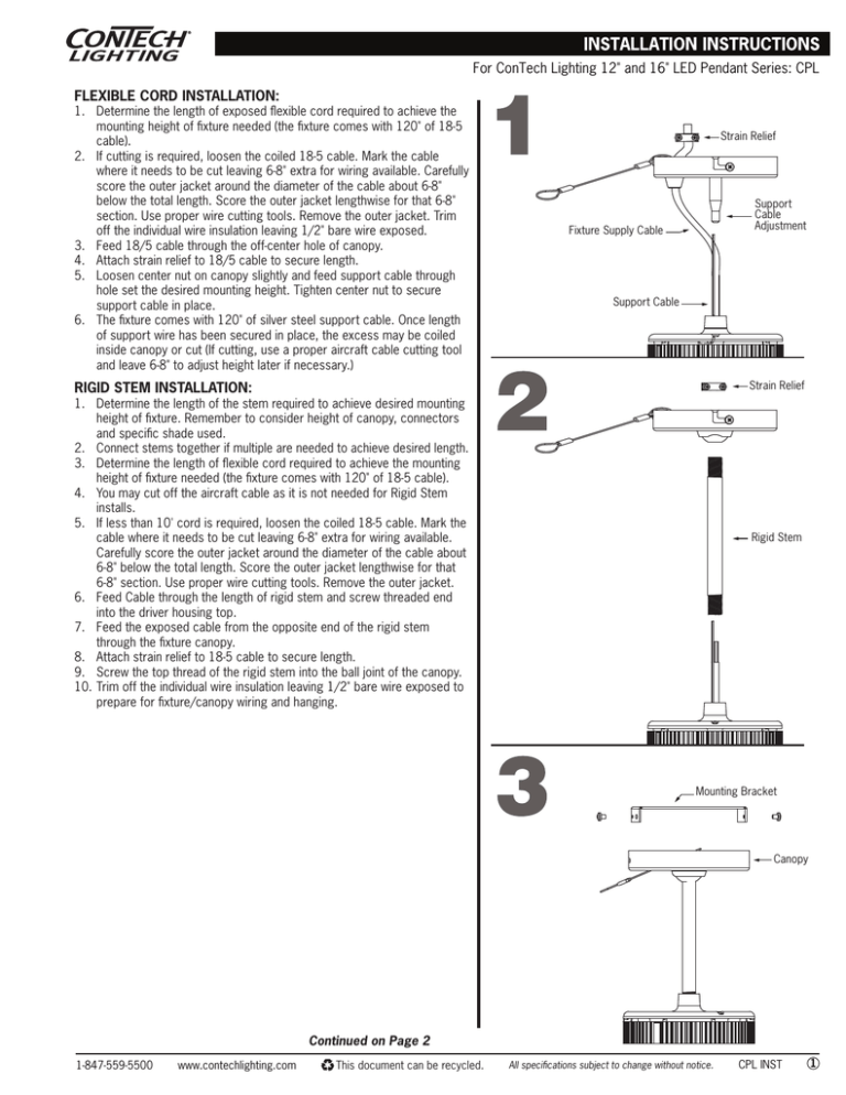
For ConTech Lighting 12" and 16" LED Pendant Series: CPL FLEXIBLE CORD INSTALLATION: 1. Determine the length of exposed flexible cord required to achieve the mounting height of fixture needed (the fixture comes with 120" of 18-5 cable). 2. If cutting is required, loosen the coiled 18-5 cable. Mark the cable where it needs to be cut leaving 6-8" extra for wiring available. Carefully score the outer jacket around the diameter of the cable about 6-8" below the total length. Score the outer jacket lengthwise for that 6-8" section. Use proper wire cutting tools. Remove the outer jacket. Trim off the individual wire insulation leaving 1/2" bare wire exposed. 3. Feed 18/5 cable through the off-center hole of canopy. 4. Attach strain relief to 18/5 cable to secure length. 5. Loosen center nut on canopy slightly and feed support cable through hole set the desired mounting height. Tighten center nut to secure support cable in place. 6. The fixture comes with 120" of silver steel support cable. Once length of support wire has been secured in place, the excess may be coiled inside canopy or cut (If cutting, use a proper aircraft cable cutting tool and leave 6-8" to adjust height later if necessary.) Strain Relief Support Cable Adjustment Fixture Supply Cable Support Cable Strain Relief RIGID STEM INSTALLATION: 1. Determine the length of the stem required to achieve desired mounting height of fixture. Remember to consider height of canopy, connectors and specific shade used. 2. Connect stems together if multiple are needed to achieve desired length. 3. Determine the length of flexible cord required to achieve the mounting height of fixture needed (the fixture comes with 120" of 18-5 cable). 4. You may cut off the aircraft cable as it is not needed for Rigid Stem installs. 5. If less than 10' cord is required, loosen the coiled 18-5 cable. Mark the cable where it needs to be cut leaving 6-8" extra for wiring available. Carefully score the outer jacket around the diameter of the cable about 6-8" below the total length. Score the outer jacket lengthwise for that 6-8" section. Use proper wire cutting tools. Remove the outer jacket. 6. Feed Cable through the length of rigid stem and screw threaded end into the driver housing top. 7. Feed the exposed cable from the opposite end of the rigid stem through the fixture canopy. 8. Attach strain relief to 18-5 cable to secure length. 9. Screw the top thread of the rigid stem into the ball joint of the canopy. 10. Trim off the individual wire insulation leaving 1/2" bare wire exposed to prepare for fixture/canopy wiring and hanging. Rigid Stem Mounting Bracket Canopy Continued on Page 2 1-847-559-5500 www.contechlighting.com This document can be recycled. All specifications subject to change without notice. CPL INST 1 For ConTech Lighting 12" and 16" LED Pendant Series: CPL • Read all the instructions before installation. Save instructions for later use. • Turn off power at fuse or circuit breaker box before installation of before doing any maintenance work. • Wear rubber soled shoes and work should be done on a sturdy wooden or non-conductive ladder. • Product must be mounted in locations and at heights in a manner consistent with its intended use, and in compliance with National Electrical Code and local building codes. For indoor use only. • Product must be grounded to avoid potential electric shock and any other potential hazards. • Do not exceed the nominal supply voltage or amperage ratings. • Make sure all screws are properly tightened. • Do not install any lamp holder closer than 6" from any curtain or similar combustible material. • Use only fixtures and fittings intended for use with ConTech Decorative Stemlight Pendant systems. • Installing contrary to instructions may cause unsafe conditions. • Warning: Risk of fire. Most dwellings built before 1985 have supply wire rated at 60˚C. Consult a qualified electrician before installation. • Warning: Risk of burns. Lamps are extremely hot when lit. Allow lamps to cool down in temperature before handling. • To avoid hazards to children, account for all parts and properly dispose of all packing materials. • Call the Technical Support department at ConTech Lighting with any installation questions: 847-559-5500. Continued on Page 3 www.contechlighting.com (2) Side Screws Green Mounting Bar Grey (Dim −) Purple (Dim +) Only use for the dimming circuit Strain Relief Bracket 18-5 Cable Canopy 5a IMPORTANT SAFETY INSTRUCTIONS: 1-847-559-5500 4 Ceiling Junction Box White Prior to installation, ensure a 4" Round or Square (with a Squareto-Round Junction Box Cover Plate) Box is properly mounted to the ceiling structure. 1. Loosen the two (2) side screws on the canopy (Figure 3), unhook mounting assist cable and remove mounting bracket from the canopy. 2. Attach the mounting bracket to junction box. 3. Position canopy and pendant assembly close to mounting bracket and reconnect mounting assist cable. (This will allow for hands free wiring) 4. Connect the leads from the junction box to the leads of the fixture (Black-to-Black, White-to-White and Green-to-Ground). 5. If using 0-10V dimming system, connect purple and gray wires per the dimmer instructions. Otherwise, use wire connector to cap these wires individually. 6. Carefully tuck excess wires and connectors in Junction Box while positioning the canopy in place. Twist and lock canopy and tighten side screws to complete assembly. 7. For RDE Remote Driver Option, wire fixture to remote driver box per Figure 5a. 8. For RDB Remote Driver Option, wire fixture to remote driver and battery back-up box per Figure 5b. Black CANOPY INSTALLATION/ELECTRICAL CONNECTION Power Supply Green Red Remote Driver Green Black White Black 5b Battery Pack Whip Fixture Junction Box Remote Driver Box Orange Yellow Black 18-2 Cable from LED Pendant This document can be recycled. White Black Driver All specifications subject to change without notice. CPL INST 2 For ConTech Lighting 12" and 16" LED Pendant Series: CPL SHADE INSTALLATIONS FIGURE 6: All 12” Decorative Glass Shades, All 12” and 16” Acrylic or Aluminum Reflectors 1. Position fixture assembly upside down on styrofoam packaging 2. Remove three (3) screws from bottom of heat sink 3. As in figure 6a, Place aluminum shroud on heat sink, then shade, then retaining plate. 4. Using the three (3) screws included with the shade, secure shade onto heat sink If adding Decorative Leg Kit (Deco-P,S, or B) continue to step 5 5. Place three legs in driver housing groove as shown in figure 6b 6. Position decorative ring below shade and secure to legs using three (3) mounting stems 7. Position bottom glass lens below ring and secure using three (3) decorative screw caps 6a Legs Shroud Figure 7: CRM12 and CRW12 Clear Specular Metal Medium or Wide 12” Reflectors 1. Position fixture assembly upside down on styrofoam packaging 2. Remove three (3) screws from bottom of heat sink 3. Secure Reflector to heat sink using three (3) screws. For Glass Cylinder Shades or Metal Shades WITHOUT Light Pipe Option 1. Position fixture assembly upside down on styrofoam packaging 2. Remove three (3) screws from bottom of heat sink 3. Secure shade mounting ring (a) to bottom of heat sink with three (3) screws 4. Position shades with side holes aligned with mounting ring holes and secure with the three (3) decorative mounting stems (b) Retaining Plate 6b Ring Lens 7 Reflector For Metal Cylinder Shades with Light Pipe Option 1. Position fixture assembly upside down on styrofoam packaging 2. Remove three (3) screws from bottom of heat sink 3. Secure shade mounting ring (a) and Light pipe mounting bracket (c) to bottom of heat sink with three (3) screws 4. Position metal shade with side holes aligned with mounting ring holes and secure with the three (3) decorative mounting stems (b) 5. Screw Light Pipe into mounting bracket. 8 Cylinder Optional Light Pipe Mounting Bracket Mounting Stems 1-847-559-5500 www.contechlighting.com This document can be recycled. All specifications subject to change without notice. CPL INST 3

