Math 2270-003 Computer Lab 2
advertisement
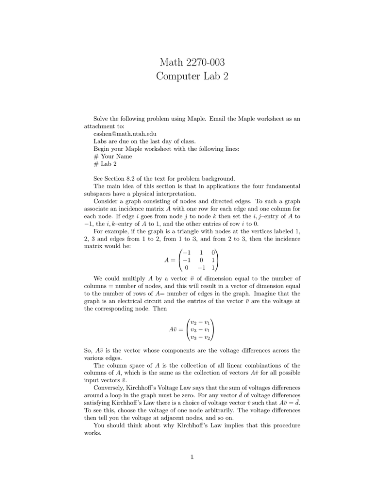
Math 2270-003 Computer Lab 2 Solve the following problem using Maple. Email the Maple worksheet as an attachment to: cashen@math.utah.edu Labs are due on the last day of class. Begin your Maple worksheet with the following lines: # Your Name # Lab 2 See Section 8.2 of the text for problem background. The main idea of this section is that in applications the four fundamental subspaces have a physical interpretation. Consider a graph consisting of nodes and directed edges. To such a graph associate an incidence matrix A with one row for each edge and one column for each node. If edge i goes from node j to node k then set the i, j–entry of A to −1, the i, k–entry of A to 1, and the other entries of row i to 0. For example, if the graph is a triangle with nodes at the vertices labeled 1, 2, 3 and edges from 1 to 2, from 1 to 3, and from 2 to 3, then the incidence matrix would be: −1 1 0 A = −1 0 1 0 −1 1 We could multiply A by a vector v̄ of dimension equal to the number of columns = number of nodes, and this will result in a vector of dimension equal to the number of rows of A= number of edges in the graph. Imagine that the graph is an electrical circuit and the entries of the vector v̄ are the voltage at the corresponding node. Then v2 − v1 Av̄ = v3 − v1 v3 − v2 So, Av̄ is the vector whose components are the voltage differences across the various edges. The column space of A is the collection of all linear combinations of the columns of A, which is the same as the collection of vectors Av̄ for all possible input vectors v̄. Conversely, Kirchhoff’s Voltage Law says that the sum of voltages differences around a loop in the graph must be zero. For any vector d¯ of voltage differences ¯ satisfying Kirchhoff’s Law there is a choice of voltage vector v̄ such that Av̄ = d. To see this, choose the voltage of one node arbitrarily. The voltage differences then tell you the voltage at adjacent nodes, and so on. You should think about why Kirchhoff’s Law implies that this procedure works. 1 So, the column space of A has a physical interpretation as the set of voltage differences satisfying Kirchhoff’s Voltage Law. The Nullspace of A is the vectors that give zero voltage difference across each edge. This is true if and only if all the voltages are the same, so the nullspace is the one dimensional space consisting of vectors with all components equal. Ohm’s Law says that Voltage = Current × Resistance. If we assume that each edge has resistance 1Ω (1 Ohm) then the current through the edge in Amps is equal to the voltage difference across the edge in Volts. Kirchhoff’s Current Law says that the current flowing in to node equals the current flowing out. If c̄ is a vector whose components are the currents through the various edges, then −1 −1 0 c1 −c1 − c2 0 −1 c2 = c1 − c3 AT c̄ = 1 0 1 1 c3 c2 + c3 Kirchhoff’s Current Law is satisfied if and only if AT c̄ = 0̄, so the Left Nullspace of A has a physical interpretation, it is the vectors whose components are currents satisfying this Law. Now suppose that we introduce an external current s flowing into node 1 and ground node 3. The grounded node has voltage zero, and has net current s flowing out. For the other nodes, the current flowing in matches the current flowing out, so the circuit satisfies the equation: s AT Av̄ = 0 −s We can find the voltage at each node by solving this equation. Recall that we know the nullspace is one dimensional, so there is exactly one free column. We have grounded a node, which means we have set the free variable v3 = 0, and we then solve for a particular solution. Finally, we could have different resistances across the edges. We account for this using a square matrix C whose i, i entry is resistance1 of edge i . Suppose edge 3 has resistance 2Ω. Then: 1 0 0 C = 0 1 0 0 0 21 To find the voltages solve the equation: v1 s AT CA v2 = 0 0 −s Then, once the voltages are known, find the currents through each edge by computing CAv̄. 2 Problem: For the following network diagram, find the voltage at each numbered node and the current flow across each numbered edge, given the following assumptions: The resistance across each edge is 1Ω except for e2 and e9, which have resistance 5Ω. There is a current of 12A that enters node 1 from the top, and a current of 12A the exits node 7 from the bottom. 3


