Evaluation Board User Guide UG-130
advertisement
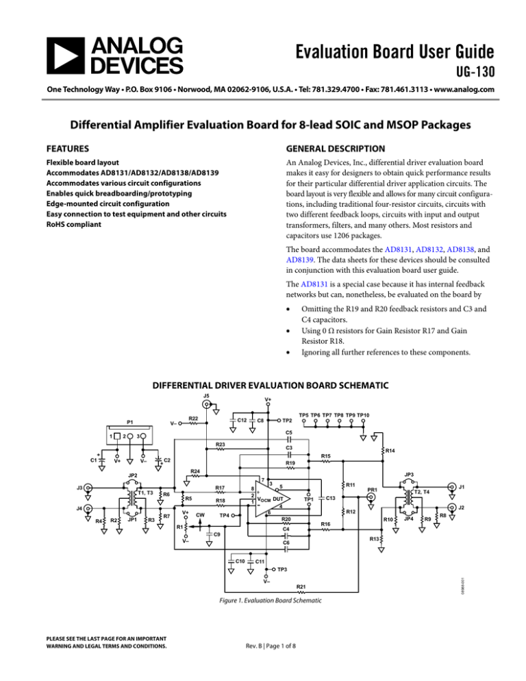
Evaluation Board User Guide UG-130 One Technology Way • P.O. Box 9106 • Norwood, MA 02062-9106, U.S.A. • Tel: 781.329.4700 • Fax: 781.461.3113 • www.analog.com Differential Amplifier Evaluation Board for 8-lead SOIC and MSOP Packages FEATURES GENERAL DESCRIPTION Flexible board layout Accommodates AD8131/AD8132/AD8138/AD8139 Accommodates various circuit configurations Enables quick breadboarding/prototyping Edge-mounted circuit configuration Easy connection to test equipment and other circuits RoHS compliant An Analog Devices, Inc., differential driver evaluation board makes it easy for designers to obtain quick performance results for their particular differential driver application circuits. The board layout is very flexible and allows for many circuit configurations, including traditional four-resistor circuits, circuits with two different feedback loops, circuits with input and output transformers, filters, and many others. Most resistors and capacitors use 1206 packages. The board accommodates the AD8131, AD8132, AD8138, and AD8139. The data sheets for these devices should be consulted in conjunction with this evaluation board user guide. The AD8131 is a special case because it has internal feedback networks but can, nonetheless, be evaluated on the board by • • • Omitting the R19 and R20 feedback resistors and C3 and C4 capacitors. Using 0 Ω resistors for Gain Resistor R17 and Gain Resistor R18. Ignoring all further references to these components. DIFFERENTIAL DRIVER EVALUATION BOARD SCHEMATIC J5 2 TP5 TP6 TP7 TP8 TP9 TP10 R22 P1 1 V+ C12 V– TP2 C8 C5 3 R23 + C1 V+ V– + C3 R19 R24 JP2 JP3 7 J3 R6 J4 R4 JP1 R3 R7 R5 V+ R18 CW 3 5 8 2 VOCM DUT 1 4 6 R20 R17 T1, T3 R2 R14 R15 C2 TP4 R11 T2, T4 J2 R12 R10 R16 R1 J1 PR1 C13 TP1 JP4 R9 R8 C4 C9 V– R13 C6 C10 C11 R21 Figure 1. Evaluation Board Schematic PLEASE SEE THE LAST PAGE FOR AN IMPORTANT WARNING AND LEGAL TERMS AND CONDITIONS. Rev. B | Page 1 of 8 08988-001 TP3 V– UG-130 Evaluation Board User Guide TABLE OF CONTENTS Features .............................................................................................. 1 Measuring Output Common-Mode Voltage .............................3 General Description ......................................................................... 1 Input/Output Transformers .........................................................3 Differential Driver Evaluation Board Schematic.......................... 1 SMA Input/Output Connectors ..................................................4 Revision History ............................................................................... 2 Other Components .......................................................................4 Evaluation Board Hardware ............................................................ 3 Evaluation Board Artwork ...............................................................5 Power Supplies .............................................................................. 3 Ordering Information.......................................................................8 Feedback Networks and Input/Output Terminations ............. 3 Related Links......................................................................................8 VOCM Input ..................................................................................... 3 REVISION HISTORY 6/10—Rev. A to Rev. B Document Title Changed from EVAL-ADDIFFAMP to UG-130.................................................................................Universal Changes to Features Section............................................................ 1 Deleted Ordering Guide .................................................................. 4 Added Evaluation Board Artwork Section ................................... 5 Added Figure 2 to Figure 13; Renumbered Sequentially ............ 5 Added Table 1; Renumbered Sequentially .................................... 8 Added Related Links Section .......................................................... 8 1/06—Rev. 0 to Rev. A Updated Format..................................................................Universal Change to Figure 1 ........................................................................... 1 10/03—Revision 0: Initial Version Rev. B | Page 2 of 8 Evaluation Board User Guide UG-130 EVALUATION BOARD HARDWARE POWER SUPPLIES VOCM INPUT Power is applied to the board through P1, a Molex® 3-pin header, Part 22-11-2032. Pin 1 (square footprint) is for the positive supply, Pin 3 is for the negative supply, and Pin 2 is connected to the ground plane of the board. Alternatively, looped test points can be used; Test Point TP2 connects to the positive supply, TP3 connects to the negative supply, and TP7 and TP8 connect to the ground plane. The TP5, TP6, TP9, and TP10 test points also connect to the ground plane. The VOCM input can be set to a dc level by adjusting the R1 potentiometer that spans the power supplies. For the dc case, C9 is provided at the wiper for decoupling. The board accommodates single or dual supplies. For singlesupply operation, connect the negative supply to the ground plane. It is very important that the power supply pins of the device under test (DUT) have broadband decoupling circuitry. The board layout facilitates this with footprints for two 1206 ceramic capacitors on each supply. At frequencies beyond the resonant frequency of the first capacitor and its associated internal and external inductance, the second capacitor provides the required low impedance return current path. For optimum performance, place the smaller of the two capacitances closest to the DUT, in the C8 and C11 positions. C13 provides the user with the option of adding differential decoupling between the supplies. Bulk decoupling is provided by C1 and C2; 10 μF tantalum capacitors are recommended. FEEDBACK NETWORKS AND INPUT/OUTPUT TERMINATIONS R19 and R17 compose the upper resistive feedback loop (see Figure 1), and R20 and R18 compose the lower feedback loop. C3 and C4 are included across the feedback resistors to provide frequency-dependent feedback, typically used to introduce a real-axis pole in the closed-loop frequency response. To minimize summing node capacitances, void the ground plane under and around Pin 1 and Pin 8 of the DUT and the copper that connects to them. R6 and R7 are included as input termination resistors for applications that have single-ended inputs. Having a place for a shunt resistor on each input makes it simple to match the two feedback factors. A common example of how this is used is when the input signal originates from an unbalanced 50 Ω source. In this case, the single-ended termination resistance is 50 Ω and the Thevenin equivalent resistance seen looking back to the source is 25 Ω. For the traditional four-resistor configuration, where R19 = R20 and R17 = R18, the feedback networks are matched by making the shunt resistor on the input leg opposite the termination resistor equal to 25 Ω. R5 is provided for differential termination. An external voltage can be applied to VOCM via TP4 (referenced to the ground plane of the board). In ADC driving applications, it is convenient to apply the ADC dc reference voltage output directly to TP4. It is also possible to drive the VOCM input from an external ac source. In this case, omit C9 or reduce it to a value that allows the desired signal to be passed. For high frequency signals on VOCM, connect the center conductor of a coaxial cable to TP4 and ground its shield at TP10. R21 is provided for the high common-mode output impedance application illustrated in the AD8132 data sheet. MEASURING OUTPUT COMMON-MODE VOLTAGE The internal common-mode feedback loop used in the differential drivers forces the output common-mode voltage to be equal to the voltage applied to the VOCM input, thereby providing excellent output balance. R11 and R12 form a voltage divider across the differential output, and the voltage at the divider tap is equal to the output common-mode voltage, provided that R11 and R12 are exactly matched in value. If R11 and R12 are used to evaluate the output common-mode voltage, they should be measured and matched to better than 300 ppm to obtain results commensurate with the DUT output balance error performance of −70 dB. Test Point PR1 accepts coaxial-type oscilloscope test points, such as the Berg Electronics 33JR135-1. INPUT/OUTPUT TRANSFORMERS The board has the added flexibility of allowing the user to incorporate transformers on its input and output. This capability can be especially useful when connecting to single-ended test equipment. Because both input and output transformers have dual, nested footprints, the user can select from a wide array of transformers available from companies such as Mini-Circuits® and Coilcraft®. The layout provides footprints for connecting resistors to ground on the primary and secondary transformer center taps, offering the user a number of options with regard to the common-mode properties of the evaluation circuit. JP1, JP2, JP3, and JP4 are jumpers on the backside of the board that provide direct shunts across their associated transformers. When not using a transformer, bypassing the transformer is a simple matter of shorting the appropriate jumpers. When using a transformer, it is a good idea to verify that the associated jumpers are open. R15 and R16 series termination resistors are provided on each of the outputs for impedance matching, analog-to-digital converter (ADC) driving, and other system requirements. Rev. B | Page 3 of 8 UG-130 Evaluation Board User Guide SMA INPUT/OUTPUT CONNECTORS The inputs and outputs have edge-mounted SMA connectors for straightforward connection to coaxial cables. The recommended connector type is Johnson Components™ Part Number 142-0701-801, or equivalent. OTHER COMPONENTS The components described in this user guide pertain mostly to traditional amplifier topologies. Footprints are provided for a number of other components on the board to allow the user to be more creative than the traditional designs. A component labeled as a capacitor need not be a capacitor provided that it fits the user’s application circuit and the footprint on the board. In application circuits where footprints for desired components are not available on the board, the user is encouraged to find ways to include them. For example, if an additional shunt element is required, the user can scrape some solder mask away from the ground plane and trace (if necessary) to make a place for the additional part. Furthermore, 1206 elements can be stacked on top of each other to implement a parallel circuit. An example of this includes stacking capacitors across R17 and R18 to realize a zero in the closed-loop transfer function. This is one way to insert preemphasis in a line-driver application. Rev. B | Page 4 of 8 Evaluation Board User Guide UG-130 Figure 2. EVAL-ADDIFFAMP-RMZ, Component Side (MSOP) 08988-004 08988-002 EVALUATION BOARD ARTWORK Figure 3. EVAL-ADDIFFAMP-1RZ, Component Side (SOIC) 08988-005 08988-003 Figure 4. EVAL-ADDIFFAMP-RMZ, Circuit Side (MSOP) Figure 5. EVAL-ADDIFFAMP-1RZ, Circuit Side (SOIC) Rev. B | Page 5 of 8 Evaluation Board User Guide 08988-007 Figure 8. EVAL-ADDIFFAMP-RMZ, Circuit Side (MSOP) 08988-006 Figure 6. EVAL-ADDIFFAMP-RMZ, Component Side (MSOP) 08988-011 08988-010 UG-130 Figure 7. EVAL-ADDIFFAMP-1RZ, Component Side (SOIC) Figure 9. EVAL-ADDIFFAMP-1RZ, Circuit Side (SOIC) Rev. B | Page 6 of 8 UG-130 08988-009 08988-008 Evaluation Board User Guide Figure 12. EVAL-ADDIFFAMP-RMZ, Circuit Side (MSOP) 08988-013 08988-012 Figure 10. EVAL-ADDIFFAMP-RMZ, Component Side (MSOP) Figure 11. EVAL-ADDIFFAMP-1RZ, Component Side (SOIC) Figure 13. EVAL-ADDIFFAMP-1RZ, Circuit Side (SOIC) Rev. B | Page 7 of 8 UG-130 Evaluation Board User Guide ORDERING INFORMATION Table 1. Bill of Materials Qty 2 10 5 4 1 1 1 23 2 2 1 9 1 1 Reference Designator C1, C2 C3 to C6, C8 to C13 J1 to J5 JP1 to JP4 P1 PR1 R1 R2 to R24 T1, T2 T3, T4 TP1 TP2 to TP10 U1 PC board Package 3216 C1206 SMASMT JPRSLD02 PWR_CONN_6-9-2 SMACON 3299W R1206 ETC1-6 KK81 TP TP104 8-lead SOIC and MSOP Description 10 μF capacitor Capacitor, user-defined value SMA connector Jumper 3-pin header, Molex Part 22-11-2032 SMA connector 1 kΩ potentiometer Resistor, user defined value Transformer Transformer Test point Test point Device under test RELATED LINKS Resource AD8131 AD8132 AD8138 AD8139 Description Product Page, AD8131 Low Cost, High Speed Differential Driver Product Page, AD8132 Low Cost, High Speed Differential Amplifier Product Page, AD8138 Low Distortion Differential ADC Driver Product Page, AD8139 Low Noise, Rail-to-Rail, Differential ADC Driver ESD Caution ESD (electrostatic discharge) sensitive device. Charged devices and circuit boards can discharge without detection. Although this product features patented or proprietary protection circuitry, damage may occur on devices subjected to high energy ESD. Therefore, proper ESD precautions should be taken to avoid performance degradation or loss of functionality. Legal Terms and Conditions By using the evaluation board discussed herein (together with any tools, components documentation or support materials, the “Evaluation Board”), you are agreeing to be bound by the terms and conditions set forth below (“Agreement”) unless you have purchased the Evaluation Board, in which case the Analog Devices Standard Terms and Conditions of Sale shall govern. Do not use the Evaluation Board until you have read and agreed to the Agreement. Your use of the Evaluation Board shall signify your acceptance of the Agreement. This Agreement is made by and between you (“Customer”) and Analog Devices, Inc. (“ADI”), with its principal place of business at One Technology Way, Norwood, MA 02062, USA. Subject to the terms and conditions of the Agreement, ADI hereby grants to Customer a free, limited, personal, temporary, non-exclusive, non-sublicensable, non-transferable license to use the Evaluation Board FOR EVALUATION PURPOSES ONLY. Customer understands and agrees that the Evaluation Board is provided for the sole and exclusive purpose referenced above, and agrees not to use the Evaluation Board for any other purpose. Furthermore, the license granted is expressly made subject to the following additional limitations: Customer shall not (i) rent, lease, display, sell, transfer, assign, sublicense, or distribute the Evaluation Board; and (ii) permit any Third Party to access the Evaluation Board. As used herein, the term “Third Party” includes any entity other than ADI, Customer, their employees, affiliates and in-house consultants. The Evaluation Board is NOT sold to Customer; all rights not expressly granted herein, including ownership of the Evaluation Board, are reserved by ADI. CONFIDENTIALITY. This Agreement and the Evaluation Board shall all be considered the confidential and proprietary information of ADI. Customer may not disclose or transfer any portion of the Evaluation Board to any other party for any reason. Upon discontinuation of use of the Evaluation Board or termination of this Agreement, Customer agrees to promptly return the Evaluation Board to ADI. ADDITIONAL RESTRICTIONS. Customer may not disassemble, decompile or reverse engineer chips on the Evaluation Board. Customer shall inform ADI of any occurred damages or any modifications or alterations it makes to the Evaluation Board, including but not limited to soldering or any other activity that affects the material content of the Evaluation Board. Modifications to the Evaluation Board must comply with applicable law, including but not limited to the RoHS Directive. TERMINATION. ADI may terminate this Agreement at any time upon giving written notice to Customer. Customer agrees to return to ADI the Evaluation Board at that time. LIMITATION OF LIABILITY. THE EVALUATION BOARD PROVIDED HEREUNDER IS PROVIDED “AS IS” AND ADI MAKES NO WARRANTIES OR REPRESENTATIONS OF ANY KIND WITH RESPECT TO IT. ADI SPECIFICALLY DISCLAIMS ANY REPRESENTATIONS, ENDORSEMENTS, GUARANTEES, OR WARRANTIES, EXPRESS OR IMPLIED, RELATED TO THE EVALUATION BOARD INCLUDING, BUT NOT LIMITED TO, THE IMPLIED WARRANTY OF MERCHANTABILITY, TITLE, FITNESS FOR A PARTICULAR PURPOSE OR NONINFRINGEMENT OF INTELLECTUAL PROPERTY RIGHTS. IN NO EVENT WILL ADI AND ITS LICENSORS BE LIABLE FOR ANY INCIDENTAL, SPECIAL, INDIRECT, OR CONSEQUENTIAL DAMAGES RESULTING FROM CUSTOMER’S POSSESSION OR USE OF THE EVALUATION BOARD, INCLUDING BUT NOT LIMITED TO LOST PROFITS, DELAY COSTS, LABOR COSTS OR LOSS OF GOODWILL. ADI’S TOTAL LIABILITY FROM ANY AND ALL CAUSES SHALL BE LIMITED TO THE AMOUNT OF ONE HUNDRED US DOLLARS ($100.00). EXPORT. Customer agrees that it will not directly or indirectly export the Evaluation Board to another country, and that it will comply with all applicable United States federal laws and regulations relating to exports. GOVERNING LAW. This Agreement shall be governed by and construed in accordance with the substantive laws of the Commonwealth of Massachusetts (excluding conflict of law rules). Any legal action regarding this Agreement will be heard in the state or federal courts having jurisdiction in Suffolk County, Massachusetts, and Customer hereby submits to the personal jurisdiction and venue of such courts. The United Nations Convention on Contracts for the International Sale of Goods shall not apply to this Agreement and is expressly disclaimed. ©2010 Analog Devices, Inc. All rights reserved. Trademarks and registered trademarks are the property of their respective owners. UG08988-0-6/10(B) Rev. B | Page 8 of 8
