Droplet absorption by a capillary channel for microgravity phase separation Kelsey Cline
advertisement
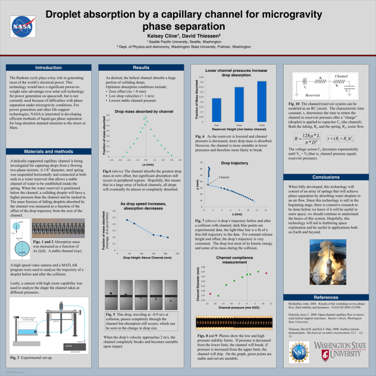
Droplet absorption by a capillary channel for microgravity phase separation Kelsey Cline1, David Thiessen2 Seattle Pacific University, Seattle, Washington 2 Dept. of Physics and Astronomy, Washington State University, Pullman, Washington 1 Results Introduction Materials and methods 0.45 Fraction of Mass Absorbed As desired, the helical channel absorbs a large portion of colliding drops. Optimum absorption conditions include: • Zero offset (∆x = 0 mm) • Low drop velocities (< 1 m/s) • Lowest stable channel pressure Drop mass absorbed by channel Fraction of mass absorbed The Rankine cycle plays a key role in generating most of the world’s electrical power. This technology would have a significant power-toweight ratio advantage over solar cell technology for power generation on spacecraft, but is not currently used because of difficulties with phase separation under microgravity conditions. For power generation and other life-support technologies, NASA is interested in developing efficient methods of liquid-gas phase separation for long-duration manned missions to the moon or Mars. Lower channel pressures increase drop absorption 0.8 Rr 0.4 0.35 Cc Reservoir 0.25 0.2 Fig. 10 The channel/reservoir system can be modeled as an RC circuit. The characteristic time constant, τ, determines the time to return the channel to reservoir pressure after a “charge” (droplet) is applied to capacitor Cc (the channel). Both the tubing, Rt, and the spring, Rc, resist flow. 0.15 0.1 0.05 0 5mm 0.6 10mm 15mm Reservoir Height (mm below channel) 0.5 Fig. 6 As the reservoir is lowered and channel pressure is decreased, more drop mass is absorbed. However, the channel is more unstable at lower pressures and therefore more likely to break. 0.3 0.2 0.1 0 Figs. 1 and 2 Absorption mass was measured as a function of ∆x (left). A stable channel (top). -4.0 -3.0 -2.0 -1.0 0.0 1.0 2.0 3.0 4.0 50 40 30 10 As drop speed increases, absorption decreases 0 0 2 4 6 8 10 12 14 x (mm) 0.5 Fig. 7 (above) A drop’s trajectory before and after a collision with channel; dark blue points are experimental data, the light blue line is a fit of a free-fall trajectory to the data. For constant release height and offset, the drop’s trajectory is very consistent. The drop lost most of its kinetic energy and some of its mass during the collision. 0.4 0.3 0.2 0.1 0 0 50 100 150 200 Channel compliance measurement Channel Diameter (mm) A high-speed video camera and a MATLAB program were used to analyze the trajectory of a droplet before and after the collision. Lastly, a camera with high zoom capability was used to analyze the shape the channel takes at different pressures. 3.09 3.07 3.05 3.03 3.01 2.99 References 2.97 2.95 -25 -20 -15 -10 -5 0 5 10 15 Channel pressure (mm H2O) Fig. 5 This drop, traveling at ~0.9 m/s at collision, passes completely through the channel but absorption still occurs, which can be seen in the change in drop size. When the drop’s velocity approaches 2 m/s, the channel completely breaks and becomes unstable upon impact. TEMPLATE DESIGN © 2008 www.PosterPresentations.com When fully developed, this technology will consist of an array of springs that will achieve phase separation by absorbing water droplets in an air flow. Since this technology is still in the beginning stage, there is extensive research to be done before we know if it will be useful in outer space; we should continue to understand the basics of this system. Hopefully, this technology will aid in furthering space exploration and be useful in applications both on Earth and beyond. 250 Drop Height Above Channel (mm) Fig. 3 Experimental set-up. The voltage across Cc decreases exponentially until Vc = Vr (that is, channel pressure equals reservoir pressure). ` Conclusions Channel 20 0.6 τ = ( Rt + Rc )Cc 60 y (mm) Fig.4 (above) The channel absorbs the greatest drop mass at zero offset, but significant absorption still occurs in peripheral regions. Hopefully, this means that in a large array of helical channels, all drops will eventually be almost or completely absorbed. 128µ * L R= 4 π *D Drop trajectory 70 ∆x (mm) Fraction of mass absorbed (Average, -2.4<∆x<2.4mm) A helically-supported capillary channel is being investigated for capturing drops from a flowing two-phase mixture. A 1/8” diameter, steel spring was suspended horizontally and connected at both ends to a water reservoir that allows a stable channel of water to be established inside the spring. When the water reservoir is positioned below the channel, a colliding droplet will have a higher pressure than the channel and be sucked in. The mass fraction of falling droplets absorbed by the channel was measured as a function of the offset of the drop trajectory from the axis of the channel. Rc Vr 0.3 0.7 0.4 Channel McQuillen, John. 2003. Results of the workshop on two-phase flow, fluid stability and dynamics. NASA/TM 2003-212598. Oelerich, Jerry J. 2009. Open-channel capillary flow in microscale helical support structures. Master’s thesis, Washington State University. Figs. 8 and 9 Photos show the low and high pressure stability limits. If pressure is decreased from the lower limit, the channel will break; if pressure is increased from the upper limit, the channel will drip. On the graph, green points are stable and red are unstable. Thiessen, David B. and Kin F. Man. 2000. Surface tension measurement. Mechanical variables measurement 12-1 – 1213.

