AN-711 APPLICATION NOTE by Alan Li
advertisement
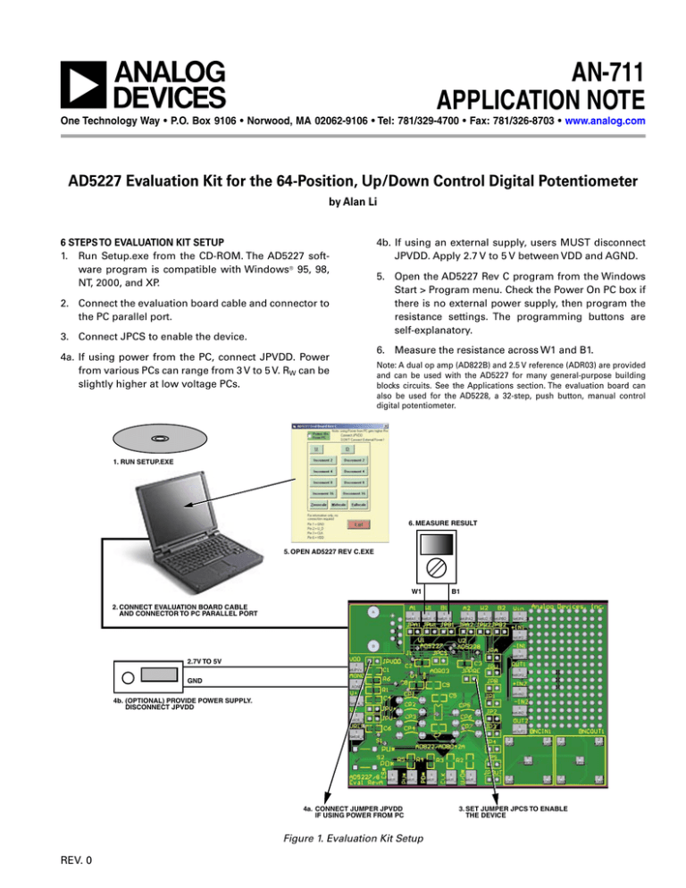
AN-711 APPLICATION NOTE One Technology Way • P.O. Box 9106 • Norwood, MA 02062-9106 • Tel: 781/329-4700 • Fax: 781/326-8703 • www.analog.com AD5227 Evaluation Kit for the 64-Position, Up/Down Control Digital Potentiometer by Alan Li 6 STEPS TO EVALUATION KIT SETUP 1. Run Setup.exe from the CD-ROM. The AD5227 software program is compatible with Windows® 95, 98, NT, 2000, and XP. 2. Connect the evaluation board cable and connector to the PC parallel port. 3. Connect JPCS to enable the device. 4a. If using power from the PC, connect JPVDD. Power from various PCs can range from 3 V to 5 V. RW can be slightly higher at low voltage PCs. 4b. If using an external supply, users MUST disconnect JPVDD. Apply 2.7 V to 5 V between VDD and AGND. 5. Open the AD5227 Rev C program from the Windows Start > Program menu. Check the Power On PC box if there is no external power supply, then program the resistance settings. The programming buttons are self-explanatory. 6. Measure the resistance across W1 and B1. Note: A dual op amp (AD822B) and 2.5 V reference (ADR03) are provided and can be used with the AD5227 for many general-purpose building blocks circuits. See the Applications section. The evaluation board can also be used for the AD5228, a 32-step, push button, manual control digital potentiometer. �� ��� ��������� �� ������� ������ �� ���� ������ ��� ����� �� �� �� ������� ���������� ����� ����� ��� ��������� �� �� �������� ���� ���� �� �� ��� ��� ���������� ������� ����� ������� ���������� ����� ��� ������� ������ ����� �� ����� ����� ���� �� Figure 1. Evaluation Kit Setup REV. 0 �� ��� ������ ���� �� ������ ��� ������ AN-711 Applications The AD5227 evaluation board comes with a dual op amp AD822, and a 2.5 V reference ADR03. Users can configure various building block circuits with minimum components. In the schematics, JP and CP stand for jumper and connection point, respectively. Figure 2. AD5227 Program Graphical Interface ��� ���� ��� ��� ��� ��� �� ���� � � �� ���� � � � � � ���� ������� �� ����� �� ��� ��� ��� �� ���� � �� ���� � �� ���� � �� ���� � ��� ��� ���� � � � �� ���� ��������� ��� � � ��� � � ���� ����� ���� �� ��� ����� �� ��� ���� � ��� ��� ��� ��� � ��� ���� �� �� ���� �� ���� �� ��� �� ������ ��� ��� � ���� ���� �� ��� ��� � ���� �� ����� �� ����� � ���� ���� ���� ��� ��� � � ������ � ���� �� ���� �� ����� ���� �� ����� ��� ���� ��� ��� �������� ���� ��������� ���� ���� �� � ���� � ���� � ���� � �� �� � ���� � ��� ���� � ��� ���� � ��� �� ���� ���� ���� ���� ��� ���� ���� ��� ��� ���� ���� ���� ���� ��� ��� ��� ��� ��� ������������� ���� �� ��� ������ � �� � � �� �� � � � � �� ������ � ������ � ����� �� ����� �� ��� ��� ��� ���� ����� ���� �� ���� �� ����� ������ �� �� ������� ��� �������� �������� �� �������� ���� �� ��� ������� Figure 3. Evaluation Board Schematic –2– REV. 0 AN-711 ��� ��� ���� ������ ���� � �� ��� ����� � �� �� ������������ � �� � ��� � � �� � �������� �� ��� � � ���� ���� ���� � �� ������� ���������� ������ ���� �������� Figure 4. 5-Bit DAC ��� ��� ���� ���� ������ �� �� � � �� ��� � �� �� �� � ������������ �� � �� � � �� ���� ��� ����� � �� ��� � �� � ��� � �� � � � � ��� ���� ���� �� Figure 5. 5-Bit DAC with Floating References for Fine Adjustment ���� ������ ��� �������� ���� ���� �� �� �� ��� � �� ���� � � � �� ��� � ��� �� � ���� ������������ � � � �� � ��� � � �� ��� ����� � �� ���� ������������ �������� ���� ���� � �� ������� ���������� ������ ���� Figure 6. Level Detector �� �� � �� ��� �� ��� �� � ���� ����� ��������� ���� �� � �� ��� � ���� �� ��� ���� � �� ��� ����� � �� ���� ���� Figure 7. Noninverting Linear Gain REV. 0 –3– � ���� � � ��� � �� � �� � � �� � �� � �� � ������� ���������� ������ AN-711 �� �� �� �� ��� ���� � ���� ���� � �� ��� � �� �� ���� � ���� � � �� � �� � � �� � �� � ���� � � �� � ��� ����� � �� ���� ������� ���������� ������ ���� Figure 8. Pseudo Log Noninverting Gain �� �� �� �� �� �� ��� �� �� � �� ��� � �� � � �� ������� ����� � �� � ��� ����� � �� ���� �� �� � � �1 �� �� �� Figure 9. Bipolar Linear Gain ������� ��� �� �� ���� ������ �� � �� ��� � �� � �� �� ����� �� � ��� � � �� ������ ���� ���� �������� ���� �� ��� ����� � �� ���� � ���� ������������ � � � �� �� ���� � ������� ���������� ������ ���� �������� ���� �������� Figure 10. Programmable 2.5 V Power Supply ��� ��� ���� ��� � �� ���� �� �� ���� � �� ��� � � �� �� ��� ��� ���� �� ���� �� ��� ����� � �� ���� ���� �� � �� ���� ���� ��� ���� �� � � ��� ���� ���� � ���� � �� ���� ������� ���������� ������ �� ���� �������� Figure 11. Programmable Current Source –4– REV. 0 AN-711 PCB Layout Figure 12. Evaluation Board Figure 13. Top Overlay REV. 0 –5– AN-711 ��� ���� �� �� �� �� �� �� �� �� �� �� �� �� �� �� �� �� �� �� � � � � � � � � �� �� ��� ��� �� �� �� �� �� �� �� � �� �� �� �� ���� � ������ ���� ��� �������� ��� ��� ���� ����� � ����� ���� �� ��������� ��� �������� ��� ������ ���� �� � ������ ���� �� ��������� ��� �������� ��� ��� ������� ����� ��� ��������� � ���� ��� ��������� �� �� ������� � ����� ������� � ����� ������� � ����� http://www.doc.ic.ac.uk/~ih/doc/par/ Figure 14. AD5227 Parallel Port Connection (for Visual Basic® Program Developers only) ��� � ��� ���� �� ��� � ��� ���� �� ������ ���� ������ �� �� �� �� �� �� � � � � �� Figure 15. Timing Example in Visual Basic Source Code (For Visual Basic program developers only. For AD5227 source code information, contact alan.li@analog.com.) –6– REV. 0 –7– AN04692–0–4/04(0) © 2004 Analog Devices, Inc. All rights reserved. Trademarks and registered trademarks are the property of their respective owners. –8–
