ECE 301 Fall Semester, 2006 HW Set
advertisement
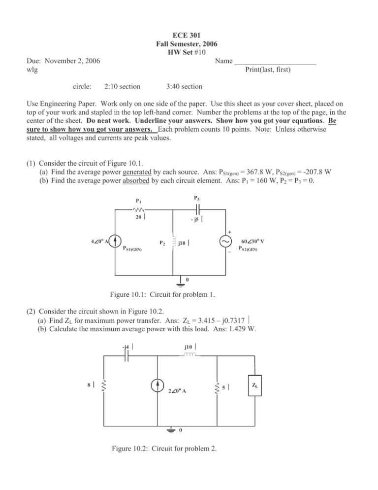
ECE 301 Fall Semester, 2006 HW Set #10 Name ______________________ Print(last, first) Due: November 2, 2006 wlg circle: 2:10 section 3:40 section Use Engineering Paper. Work only on one side of the paper. Use this sheet as your cover sheet, placed on top of your work and stapled in the top left-hand corner. Number the problems at the top of the page, in the center of the sheet. Do neat work. Underline your answers. Show how you got your equations. Be sure to show how you got your answers. Each problem counts 10 points. Note: Unless otherwise stated, all voltages and currents are peak values. (1) Consider the circuit of Figure 10.1. (a) Find the average power generated by each source. Ans: PS1(gen) = 367.8 W, PS2(gen) = -207.8 W (b) Find the average power absorbed by each circuit element. Ans: P1 = 160 W, P2 = P3 = 0. P3 P1 20 Ω - j5 Ω + 4∠ ∠0 A o P S1(GEN) P2 j10 Ω _ 60∠ ∠30o V P S2(GEN) 0 Figure 10.1: Circuit for problem 1. (2) Consider the circuit shown in Figure 10.2. (a) Find ZL for maximum power transfer. Ans: ZL = 3.415 – j0.7317 Ω (b) Calculate the maximum average power with this load. Ans: 1.429 W. -j4 Ω 8Ω j10 Ω 2∠ ∠0o A 0 Figure 10.2: Circuit for problem 2. 5Ω ZL (3) You ae given the voltage waveform shown in Figure 10.3. (a) Find the RMS value of the voltage waveform. Ans: 2.92 V (b) Find the average power absorbed by a 2 Ω resistor when the voltage is applied across the resistor. Ans: P = 4.267 W 8 v(t) V . . . 0 2 5 7 t (sec) 10 Figure 10.3: Waveform for problem 3. (4) For the power system shown in Figure 10.4 , with 220 V rms applied, find; (a) the average power. Ans: P = 1634.7 W (b) the reactive power. Ans: Q = 913.47 VA (vars) (c) the power factor. Ans: pf = 0.8732 leading + 220∠ ∠0 o V rms 60 Hz _ Loads 124∠ ∠0 o Ω 20 - j25 Ω 90 + j80 Ω Figure 10.4: Circuit for problem 4. 12 (5) For the following voltage and current phasors calculate the (i) complex power, (ii) apparent power, (iii) real power, (iiii) reactive power, (v) specify whether the pf is leading or lagging. (a) V = 220∠30o V rms, I = 0.5∠60o A rms Ans :95.26 − j 55VA,110VA, 92.26W , 55VARs, pf leading (b) V = 250∠ − 10o V rms, I = 6.2∠ − 25o A rms Ans :1497.2 + j 401.2VA, 1550VA, 1497.2W , 401.2VARs, pf lagging (c) V =120∠0o V rms, I = 2.4∠ − 15o Arms Ans :278.2 + j 74.5VA, 288VA, 278.2W , 74.54VARs, pf lagging (d ) V =160∠45o V rms, I = 8.5∠90o A rms Ans :961.7 − j 961.7 VA, 1360VA, 961.7 W , 961.7 VARs, pf leading (6) For the entire circuit of Figure 10.6 calculate: (a) the power factor, pf = .9956 lagging (b) the average power delivered by the source, P = 15.56 W (c) the reactive power, Q = 1.466 VARs (d) the apparent power, |S| = 15.63 VA (e) the complex power . S = 15.56 + j1.466 VA 2Ω + 16∠ ∠45o V _ -j5 Ω 10 Ω Figure 10.6: Circuit for problem 6. j6 Ω 8Ω (7) Find Io in the circuit of Figure 10.7. Ans: 443∠-28.13o A. Io + 220∠ ∠0o V 12 kW 0.866 pf leading 16 kW 0.85 pf lagging 20 k VARs 0.6 pf lagging _ 0 Figure 10.7: Circuit for problem 10.7. (8) An ac motor with impedance ZL = 4.2 + j3.6 Ω is supplied by a 220 V rms, 60-Hz source. (a) Find the pf, P, and Q: Ans: pf = 0.7592 lagging, P = 6.643 kW, Q = 5.695 kVARs (b) Determine the capacitor required to be connected in parallel with the motor so that the power factor is corrected to unity. Ans: C = 312 µF (9) For the network given in Figure 10.9, find the complex power absorbed by each element and the complex power supplied by the source. Ans: S supplied by the source: 5.12 + j2.56 VA S absorbed by the resistor: 5.12 VA (watts) S absorbed by capacitor: -j3.84 VA S absorbed by the inductor: j6.4 VA + -j3 Ω j5 Ω 8∠ ∠-20 o V _ 4Ω 0 Figure 10.9: Circuit for problem 9.
