AUTOMATIC REGISTRATION OF TERRESTRIAL LASER SCANNER DATA VIA IMAGERY
advertisement
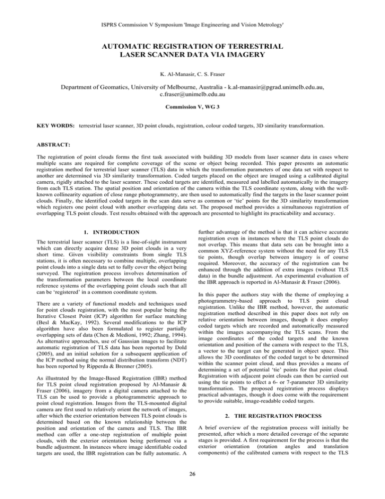
ISPRS Commission V Symposium 'Image Engineering and Vision Metrology' AUTOMATIC REGISTRATION OF TERRESTRIAL LASER SCANNER DATA VIA IMAGERY K. Al-Manasir, C. S. Fraser Department of Geomatics, University of Melbourne, Australia - k.al-manasir@pgrad.unimelb.edu.au, c.fraser@unimelb.edu.au Commission V, WG 3 KEY WORDS: terrestrial laser scanner, 3D point clouds, registration, colour coded targets, 3D similarity transformation. ABSTRACT: The registration of point clouds forms the first task associated with building 3D models from laser scanner data in cases where multiple scans are required for complete coverage of the scene or object being recorded. This paper presents an automatic registration method for terrestrial laser scanner (TLS) data in which the transformation parameters of one data set with respect to another are determined via 3D similarity transformation. Coded targets placed on the object are imaged using a calibrated digital camera, rigidly attached to the laser scanner. These coded targets are identified, measured and labelled automatically in the imagery from each TLS station. The spatial position and orientation of the camera within the TLS coordinate system, along with the wellknown collinearity equation of close range photogrammetry, are then used to automatically find the targets in the laser scanner point clouds. Finally, the identified coded targets in the scan data serve as common or ‘tie’ points for the 3D similarity transformation which registers one point cloud with another overlapping data set. The proposed method provides a simultaneous registration of overlapping TLS point clouds. Test results obtained with the approach are presented to highlight its practicability and accuracy. further advantage of the method is that it can achieve accurate registration even in instances where the TLS point clouds do not overlap. This means that data sets can be brought into a common XYZ-reference system without the need for any TLS tie points, though overlap between imagery is of course required. Moreover, the accuracy of the registration can be enhanced through the addition of extra images (without TLS data) in the bundle adjustment. An experimental evaluation of the IBR approach is reported in Al-Manasir & Fraser (2006). 1. INTRODUCTION The terrestrial laser scanner (TLS) is a line-of-sight instrument which can directly acquire dense 3D point clouds in a very short time. Given visibility constraints from single TLS stations, it is often necessary to combine multiple, overlapping point clouds into a single data set to fully cover the object being surveyed. The registration process involves determination of the transformation parameters between the local coordinate reference systems of the overlapping point clouds such that all can be ‘registered’ in a common coordinate system. In this paper the authors stay with the theme of employing a photogrammetry-based approach to TLS point cloud registration. Unlike the IBR method, however, the automatic registration method described in this paper does not rely on relative orientation between images, though it does employ coded targets which are recorded and automatically measured within the images accompanying the TLS scans. From the image coordinates of the coded targets and the known orientation and position of the camera with respect to the TLS, a vector to the target can be generated in object space. This allows the 3D coordinates of the coded target to be determined within the scanner point cloud, and thus provides a means of determining a set of potential ‘tie’ points for that point cloud. Registration with adjacent point clouds can then be carried out using the tie points to effect a 6- or 7-parameter 3D similarity transformation. The proposed registration process displays practical advantages, though it does come with the requirement to provide suitable, image-readable coded targets. There are a variety of functional models and techniques used for point clouds registration, with the most popular being the Iterative Closest Point (ICP) algorithm for surface matching (Besl & MacKay, 1992). Several modifications to the ICP algorithm have also been formulated to register partially overlapping sets of data (Chen & Medioni, 1992; Zhang, 1994). As alternative approaches, use of Gaussian images to facilitate automatic registration of TLS data has been reported by Dold (2005), and an initial solution for a subsequent application of the ICP method using the normal distribution transform (NDT) has been reported by Ripperda & Brenner (2005). As illustrated by the Image-Based Registration (IBR) method for TLS point cloud registration proposed by Al-Manasir & Fraser (2006), imagery from a digital camera attached to the TLS can be used to provide a photogrammetric approach to point cloud registration. Images from the TLS-mounted digital camera are first used to relatively orient the network of images, after which the exterior orientation between TLS point clouds is determined based on the known relationship between the position and orientation of the camera and TLS. The IBR method can offer a one-step registration of multiple point clouds, with the exterior orientation being performed via a bundle adjustment. In instances where image identifiable coded targets are used, the IBR registration can be fully automatic. A 2. THE REGISTRATION PROCESS A brief overview of the registration process will initially be presented, after which a more detailed coverage of the separate stages is provided. A first requirement for the process is that the exterior orientation (rotation angles and translation components) of the calibrated camera with respect to the TLS 26 IAPRS Volume XXXVI, Part 5, Dresden 25-27 September 2006 (mainly pixel size), field of view, the code size, the imaging scale, the obliquity of the optical axis to the target normal and the lighting conditions. Generally, the problems diminish as the imaging scale increases, which accounts for the need to accommodate more than one zoom setting within a multi-image configuration. coordinate system is known. This can be established via the well-known resection process in close range photogrammetry. A second requirement is that a sufficient number of suitable coded targets are placed on the object being surveyed such that, say, 5-8 of these will be common to adjacent scans. A third general requirement is that the selected coded targets need to be automatically detected and decoded in the images which are recorded with each laser scan. There are a number of design options for coded targets in closerange photogrammetry, and in this particular instance the colour coded targets which are used for automatic camera calibration in the iWitness system (Photometrix, 2006) have been adopted, simply because they were available and are well suited to the task. The identification of the coded targets in the imagery is constrained by the imaging scale and the target size, smaller targets always being preferred for practical reasons. Limitations in this area can be reduced somewhat by exploiting the zoom capabilities of the camera, though it is necessary to have the appropriate interior orientation and lens distortion parameters for each zoom setting employed. Each image may conceivably warrant a different zoom setting. The problem of varying calibration parameters with zoom setting has been circumvented in the proposed approach through use of so-called zoom-dependent calibration (Fraser & Al-Ajlouni, 2006), whereby the appropriate image coordinate corrections at any zoom setting are determined as a function of the lens focal length value recorded in the EXIF header of the image file. Code # 5 Code # 28 Figure 1. Example colour coded targets. 2.2 Image Coordinate Correction Image measurements of coded targets need to be first corrected for principal point offset and radial lens distortion. This is achieved via the zoom-dependent image coordinate correction model (Fraser & Al-Ajlouni, 2006) because different zoom settings will invariably be used for the different images. The correction model for zoom-dependent camera calibration is given as: After the image coordinates of the targets are corrected for the principal point offset and radial lens distortion, the collinearity condition and the exterior orientation of the camera within the TLS coordinate system are used to locate the coded targets in the TLS point cloud. The located coded targets then constitute potential tie points between adjacent scan data sets, and the provision of three or more such common points will facilitate the registration between two point clouds via 3D similarity transformation. Due to the unique codes, operator intervention is not required at any stage and this coded-target based registration can be carried out fully automatically. x corr = x − x (c ) i p y corr = y − y ( ci ) p ( )K + (y − y )K + x−x (c ) i p (c ) i 1 r2 ( ci ) ( ci ) p 1 (1) r2 where (2) ci = a0 + a1 f i Here, fi is the zoom focal length written to the EXIF header of the digital image, x,y are the measured coordinates and xcorr, ycorr are the corrected image coordinates, ci is the principal distance, x(pc ) and y(pc ) are principal point offsets, and K1(c ) is the i i i 2.1 Colour Coded Targets coefficient of radial lens distortion. Colour coded targets designed for automatic camera calibration, described in Cronk et al. (2006), have been adopted here, though any suitable code design would suffice. In the case of the 15x15cm targets illustrated in Fig. 1, the identification in image space is achieved by a scanning process that separates candidate code spots by colour saturation and brightness. 2.3 Relationship between the Camera and TLS The determination of the relative position and orientation of the camera with respect to the TLS has been described by AlManasir & Fraser (2006) and here only a short summary of the process is presented. Following a separate camera calibration process, spatial resection from selected image-identifiable scan points is employed to determine the required rotation angles and 3-axis translations. Although a minimum of three object points is necessary for the spatial resection, 10 or so well distributed points would be recommended for accuracy and reliability reasons. In order to uniquely label the codes, a decoding process is adopted, which takes into account the angular and spatial relationships of the dots and whether they are either red or green at each location. There are 32 possible combinations of the two-colour, 5-point ‘T’ pattern, though this could be extended to 243 if blue would be considered as well (Cronk et al., 2006). Once all the codes are automatically identified in the imagery, they are decoded and the two-dimensional positions of each individual dot within the code is recorded via intensityweighted centroiding. With the camera exterior orientation determined with respect to the TLS, transformation between the two Cartesian coordinate systems can be effected using the following well-known 3D conformal transformation model: In order to test the practicability and efficiency of identifying these coded targets in images recorded over a range of object distances, several tests were conducted. These indicated that for a specific focal length, the process is limited by several reasonably predictable factors, namely camera resolution ⎛ x⎞ ⎜ ⎟ ⎜ y ⎟ = λ RC ⎜z⎟ ⎝ ⎠ 27 ⎛X − Xc⎞ ⎟ ⎜ ⎜ Y −Yc ⎟ ⎜⎜ c ⎟ ⎟ ⎝Z−Z ⎠ (3) ISPRS Commission V Symposium 'Image Engineering and Vision Metrology' where (X, Y, Z) are the TLS point coordinates, the rotation matrix RC expresses the relative alignment between the axes of the two systems, and (Xc, Yc, Zc) expresses the position of the camera with respect to the origin of the TLS coordinate system. In this case the scale factor λ has unit value (unless a change of units is involved). ⎛ x′ ⎞ ⎛ x⎞ ⎜ ⎟ ⎜ ⎟ ′ y . y = R ⎜ ⎟ T ⎜ ⎟ ⎜ z′ ⎟ ⎜z⎟ ⎝ ⎠ ⎝ ⎠ (5) Here, [x, y, z]T is as in Eq 3 and the matrix RT is a 3x3 rotation matrix defining the camera rotations that allow the camera z-axis to pass through the vector p. RT is computed as 2.4 Target Location in the TLS Point Cloud Once all the coded targets are automatically identified in the imagery for each scan, they need to be identified in the object space, ie within the scanner point cloud. The well-known collinearity condition states that the perspective centre of the camera, the image point and the corresponding object point all lie along the same line, as illustrated in Fig. 2 for the perspective centre, image point ‘p’ and corresponding object point ‘P’. The direction of this line for a particular image point j is defined by the corrected image coordinates and principal distance, computed using Eqs. 1 and 2, as [xj, yj, ci]. R T = R (ω, ϕ , κ) (6) where ⎛ y ⎞ ⎟ ω = tan −1 ⎜ ⎜ c ⎟ ⎝ ⎠ ⎛ −x ⎞ ⎟ ϕ = tan −1 ⎜ ⎜ c ⎟ ⎝ ⎠ κ =0 Here x, y are the corrected image coordinates for the target and c is the corrected principal distance. 2. All scan points satisfying the following criteria are determined: x ′ ≤ Threshold and y ′ ≤ Threshold The average spacing of the TLS points is used as the threshold value. 3. The result from the previous step is used to compute the centroid of all points. This yields the object point corresponding to the image coded target. 4. This correspondence determination between image measurement and TLS scan point is carried out for all the coded targets, in all images. 2.5 Point Cloud Registration Figure 2. The geometric relationship between the camera and TLS coordinate systems. Once all codes are automatically identified in the scan data, the registration between point clouds is achieved via a least-squares solution for each 3D similarity transformation. This uses the matched TLS coordinates for the coded targets, which constitute the common points between point clouds. The basic 3D similarity transformation model is that of Eq. 3. In order to find the object point corresponding to a measured image point (coded target dot), the 3D coordinates of the TLS point cloud are first transformed into the image coordinate system. Then, for any target in the image, the corresponding point in object space will be that lying closest to the imaging ray corresponding to the vector p. The mathematical relationship between the image and object point can be expressed as follows: r r P =λ.p 3. EXPERIMENTAL VALIDATION Two trial applications of the proposed method are reported here, these having been conducted to both validate and evaluate the process. The first represented a typical task that might be undertaken with a TLS, namely the 3D measurement and modelling of a civil engineering test rig designed to simulate vibrational loading effects on brick and timber structures. From a measurement perspective, this is essentially a multi-epoch deformation monitoring survey. The second involved the scanning of the relocated historic building entry-way. (4) Since the scale factor for each individual image point is unknown due to the corresponding object point in the TLS not being known, a technique based on the collinearity condition is used to find the codes in the TLS point cloud. The corresponding object space point for a coded target point in the image space can be found as follows: 3.1 Engineering Site 1. The scan data is transformed to a new coordinate system. The origin for the new system is the perspective centre of the camera as per Figure 2, with the z-axis passing through the vector p in the camera coordinate system. This transformation can be expressed as following: The first stage of the process was to establish the relationship between the camera and TLS coordinate systems. To achieve this, the method described in Al-Manasir & Fraser (2006) was adopted. After a Canon IXUS V digital camera had been selfcalibrated at multiple focal settings, to enable application of the 28 IAPRS Volume XXXVI, Part 5, Dresden 25-27 September 2006 zoom-dependent image coordinate corrections, it was attached to a Cyrax 2500 laser scanner. The spatial position and orientation of the camera within the TLS coordinate system was then established via resection, with the resulting precision (RMS 1-sigma) being close to 0.5mm for position and 8 seconds of arc for the three orientation angles. 4 3 Four stations were employed to gather the 4 million laser points on the structural deformation test rig shown in Fig. 3, and the four associated images, each with a different zoom setting. The resulting TLS/image network is indicated in Fig. 4. Stations were selected so as to ensure sufficient overlap between scan data to support robust registration. Also, different zoom settings were employed to ensure that all coded targets were clearly identifiable and measurable within the images (See Table 1). 1 2 Figure 4. Four-scan coverage of the engineering test site. Table 2. RMSE of the ICP and proposed coded target-based registrations for the engineering test site survey. Method Number of check pts. RMSE X(mm) RMSE Y(mm) RMSE Z(mm) ICP Proposed method 50 4.1 3.8 3.0 50 2.1 1.8 2.1 Figure 3. Engineering test site. Table 1: Canon IXUS V zoom settings for the test-rig survey. Station Focal length (mm) 1, 3 2, 4 5 11 In the initial image measurement stage, all the codes were automatically identified in the imagery, and following the image coordinate correction and transformation of the TLS point cloud data into the image coordinate system (sequentially for each imaged coded target via Eq. 5), the 3D positions of targets were determined in object space. The resulting 3D similarity transformation computations produced the final, registered 3D point cloud shown in Fig. 5. (a) front In order to assess the accuracy of registered 3D coordinates obtained with the proposed coded-target method, 50 well distributed photogrammetrically measured checkpoints of 2mm accuracy were employed. These were automatically identified in the 3D models from both the proposed and ICP approaches. The resulting RMSE values for the ICP and the coded-target models, as assessed against the checkpoint coordinates, are shown in Table 2. In the context of both the accuracy of the Cyrax 2500, of about 6mm over the imaging distance, and the ability to precisely identify the checkpoints in the laser data, the results are consistent with expectations, though it is still noteworthy that the proposed method produces higher accuracy than the ICP approach. (b) rear Figure 5. The resulting laser scanned 3D model of the engineering test site. 29 ISPRS Commission V Symposium 'Image Engineering and Vision Metrology' 3.2 19th Century Building Porch The historic porch shown in Fig. 6 used to grace the entrance of a 19th century office building in the city of Melbourne, but now it forms an entrance to one of the car parks at the University of Melbourne. The porch served as the second test evaluation site for the proposed registration method based on image-measured coded targets and 3D similarity transformation. In this instance the Cyrax 2500 was again employed, this time with a Nikon D200 SLR-type digital camera mounted on the TLS. After the Nikon D200 had been calibrated, again at multiple zoom focal lengths, and attached to the laser scanner, the exterior orientation parameters of the camera within the TLS reference system were determined by resection from 20+ 3D TLS points. This yielded exterior orientation elements for the camera to a 1sigma accuracy of close to 0.3mm for position and 5 seconds of arc for the three orientation angles. Given the inherent accuracy of the TLS, the resection result was viewed as quite satisfactory for the subsequent registration and indeed was expected to produce a registration accuracy that would easily surpass that attainable using TLS data alone. Figure 7. TLS/camera station geometry for the porch survey. Five stations were employed to gather the 5 million laser points, and five images were recorded with different zoom settings to ensure that all coded targets were identifiable in the images (see Table 3). Care was also taken to ensure that there would be sufficient overlap between TLS point clouds to support robust registration (see Fig. 7). Figure 8. The resulting laser scanned 3D model of the porch. Table 4. Accuracy of the registered point cloud for the porch. Figure 6. The historic porch, showing colour-coded targets. Method Table 3. Nikon D200 zoom settings used in the porch survey. ICP Proposed method Station Focal length (mm) 1, 3 2 4 5 18 29 31 35 Number of check pts. 40 RMSE X(mm) 3.7 RMSE Y(mm) 3.6 RMSE Z(mm) 3.2 40 1.9 1.7 2.0 4. CONCLUSIONS An automatic registration method for terrestrial laser scanner data augmented with imagery from a camera mounted on the TLS has been presented. The proposed approach employs image-measured coded targets coupled with 3D similarity transformation using the determined 3D positions of the coded targets in the TLS point cloud. The proposed automatic registration approach was again performed, with the resulting 3D model being shown in Fig. 8. In order to assess the accuracy of the registered 3D coordinates obtained with the image-recorded, coded-target/3D similarity transformation method, 40 well distributed photogrammetrically measured checkpoints of 2mm accuracy were employed. These were identified in the 3D models from both the proposed method and ICP registration algorithm. The resulting RMSE values for each approach, as assessed against the checkpoint coordinates, are shown in Table 4. The resulting accuracy, in the range of 2-4mm, is consistent with expectations, though once again the proposed method produced higher accuracy than the ICP approach. In the first test application, employing a civil engineering deformation analysis test rig, the image target points were detected and measured automatically, which also facilitated automatic registration of the laser scan data. The accuracy attained in the registered point cloud via the proposed approach was at the 2mm level. In the second test survey, which represented a practical heritage recording scenario, the 3D model formed using the proposed approach was found to be in overall alignment with that obtained via an ICP, again to an 30 IAPRS Volume XXXVI, Part 5, Dresden 25-27 September 2006 Cronk, S., Fraser, C.S. and Hanley, H., 2006. Automatic calibration of colour digital cameras. Photogrammetric Record, 19 pages (in press). accuracy of a few mm. The proposed automatic registration approach has been shown to be robust, practical and capable of accuracy comparable with and even better than the ICP approach. Dold, C., 2005. Extended Gaussian images for the registration of terrestrial scan data. International Archives of the Photogrammetry, Remote Sensing and Spatial Information Sciences, 36 (3/W19): 180-186. As a final comment, the image-measured coded-target registration method follows the same philosophy as in the IBR method previously developed by the authors, namely that photogrammetric processing of imagery from the digital cameras nowadays attached to TLS systems can provide a very useful means to assist and even enhance the TLS point cloud registration process. Fraser, C.S. and Al-Ajlouni, S., 2006. Zoom-dependent camera calibration in close-range photogrammetry. Photogrammetric Engineering and Remote Sensing (in press). Photometrix, 2006. http://www.photometrix.com.au [Accessed 10th March, 2006]. 5. REFERENCES Al-Manasir, K. and Fraser, C.S., 2006. Registration of terrestrial laser scanner data using imagery. Photogrammetric Record (in press). Ripperda, N. and Brenner, C., 2005. Marker-Free Registration of terrestrial laser scans using the Normal distribution transform. International Archives of the Photogrammetry, Remote Sensing and Spatial Information Sciences, 36 (5/W17) (on CD-Rom). Besl, P.J. and McKay, N.D., 1992. A method for registration of 3-D shapes. IEEE Transactions on Pattern Analysis and Machine Intelligence, 14(2): 239-256. Zhang, Z., 1994. Iterative point matching for registration of free-form curves and surfaces. International Journal of Computer Vision, 13(2):119-152. Chen, Y. and Medioni, G., 1992. Object modelling by registration of multiple range images. Image and Vision Computing, 10(3): 145-155. 31
