EVALUATION OF STRUCTURAL DAMAGES FROM 3D LASER SCANS
advertisement
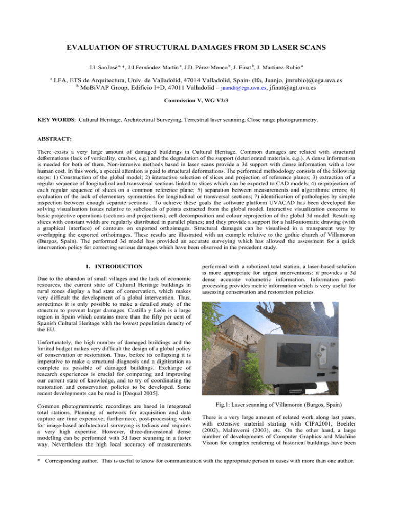
EVALUATION OF STRUCTURAL DAMAGES FROM 3D LASER SCANS J.I. SanJosé a, *, J.J.Fernández-Martín a, J.D. Pérez-Moneo b, J. Finat b, J. Martínez-Rubio a a LFA, ETS de Arquitectura, Univ. de Valladolid, 47014 Valladolid, Spain- (lfa, Juanjo, jmrubio)@ega.uva.es b MoBiVAP Group, Edificio I+D, 47011 Valladolid – juandi@ega.uva.es, jfinat@agt.uva.es Commission V, WG V2/3 KEY WORDS: Cultural Heritage, Architectural Surveying, Terrestrial laser scanning, Close range photogrammetry. ABSTRACT: There exists a very large amount of damaged buildings in Cultural Heritage. Common damages are related with structural deformations (lack of verticality, crashes, e.g.) and the degradation of the support (deteriorated materials, e.g.). A dense information is needed for both of them. Non-intrusive methods based in laser scans provide a 3d support with dense information with a low human cost. In this work, a special attention is paid to structural deformations. The performed methodology consists of the following steps: 1) Construction of the global model; 2) interactive selection of slices and projection of reference planes; 3) extraction of a regular sequence of longitudinal and transversal sections linked to slices which can be exported to CAD models; 4) re-projection of each regular sequence of slices on a common reference plane; 5) separation between measurements and algorithmic errors; 6) evaluation of the lack of elementary symmetries for longitudinal or transversal sections; 7) identification of pathologies by simple inspection between enough separate sections . To achieve these goals the software platform UVACAD has been developed for solving visualisation issues relative to subclouds of points extracted from the global model. Interactive visualization concerns to basic projective operations (sections and projections), cell decomposition and colour reprojection of the global 3d model. Resulting slices with constant width are regularly distributed in parallel planes; and they provide a support for a half-automatic drawing (with a graphical interface) of contours on exported orthoimages. Structural damages can be visualised in a transparent way by overlapping the exported orthoimages. These results are illustrated with an example relative to the gothic church of Villamoron (Burgos, Spain). The performed 3d model has provided an accurate surveying which has allowed the assessment for a quick intervention policy for correcting serious damages which have been observed in the precedent study. 1. INTRODUCTION Due to the abandon of small villages and the lack of economic resources, the current state of Cultural Heritage buildings in rural zones display a bad state of conservation, which makes very difficult the development of a global intervention. Thus, sometimes it is only possible to make a detailed study of the structure to prevent larger damages. Castilla y León is a large region in Spain which contains more than the fifty per cent of Spanish Cultural Heritage with the lowest population density of the EU. performed with a robotized total station, a laser-based solution is more appropriate for urgent interventions: it provides a 3d dense accurate volumetric information. Information postprocessing provides metric information which is very useful for assessing conservation and restoration policies. Unfortunately, the high number of damaged buildings and the limited budget makes very difficult the design of a global policy of conservation or restoration. Thus, before its collapsing it is imperative to make a structural diagnosis and a digitization as complete as possible of damaged buildings. Exchange of research experiences is crucial for comparing and improving our current state of knowledge, and to try of coordinating the restoration and conservation policies to be developed. Some recent developments can be read in [Dequal 2005]. Common photogrammetric recordings are based in integrated total stations. Planning of network for acquisition and data capture are time expensive; furthermore, post-processing work for image-based architectural surveying is tedious and requires a very high expertise. However, three-dimensional dense modelling can be performed with 3d laser scanning in a faster way. Nevertheless the high local accuracy of measurements Fig.1: Laser scanning of Villamoron (Burgos, Spain) There is a very large amount of related work along last years, with extensive material starting with CIPA2001, Boehler (2002), Malinverni (2003), etc. On the other hand, a large number of developments of Computer Graphics and Machine Vision for complex rendering of historical buildings have been * Corresponding author. This is useful to know for communication with the appropriate person in cases with more than one author. performed along last ten years. On the other hand, modern scientific visualization requires the possibility of making consults and evaluation of structural properties involving the building and other information relative to its environment. Thus, it is necessary to develop multi-resolution and hybrid approaches for architectural and environmental surveying (see e.g. El-Hakim et al, 2002). The development of interoperability tools between Surveying and Information Systems, including advanced visualization techniques models is the next challenge to solve. Advanced Visualization must allow the exchange, processing and analysis of metric information with objectoriented data and metadata bases relative to the information with a 2D/3D support. Dealing with huge number of points, it is necessary to combine a volumetric segmentation with 3D matching to different levels of detail (LoD). This combination provides a semi-automatic identification of primitives appearing in buildings for each LoD. The coarsest level of the hierarchy involves the identification of geometric elements (dominant planes, quadrics, e.g.) whereas the finest level deals with complex primitives (ornamental details, pinnacles, ledges, sculptures, e.g.). The automatic identification of complex primitives from basic geometric primitives is still a challenge for semi-automatic 3D recognition and modelling with a large number of applications to CAD, Architectural or Archaeological Surveying, computer animation and simulation, including VR/AR, between others. Currently, the LFA-MoBiVAP research group is developing information systems for Cultural Heritage included in advanced visualization systems. Post-processing of 3D information arising from sampling of huge clouds of points allows to identify the difference between the current state and ideal simple planar and quadratic primitives. Multi-resolution models have been applied for visualizing and virtual reconstructions of archaeological sites; an analysis and ideal reconstructions for the roman theater of Clvnia (Burgos, Spain) is displayed in Finat et al (2005). An extension for urban environments is developed in Fernandez, 2006. extracted from the Gothic church of Villamorón (Burgos, Spain). 2. CURRENT STATE AND DESCRIPTION OF GOALS The church of Santiago in Villamorón (Burgos, Spain) displays some structural problems related with the lack of necessary building adaptations for transition from Romanesque to the early Gothic style. Indeed, the central nave is too high for the lateral ones, some almost evident misalignments in columns along the head produce strong alterations in the structure with visible crashes in the tower. The performed work is focused towards the identification of deviations in regard to verticals for walls and misalignments for columns, their quantification and the analysis of crashes and structural defaults from the global 3d model. Fig.2: Panoramic View of the church of Villamoron (Burgos) The western facade displays an important lack of verticality, which is in the issue of two large crashes going from the roof to the ground. In the head of temple, there appear serious crashes along windows which modify the continuity and the survival of structure. Inside, the vaults are apparently full of cracks and a meaningful number of stones located along arches are down-toearth. The main goal of this work is to contribute to the semiautomatic 3D modeling and design of architectural primitives corresponding to damaged buildings from range scanning files. To achieve this goal, simpler PL-models (piecewise linear) are generated from huge unordered clouds of points captured with a laser scan device device Ilris 3D (Optech). Sections (regular slices with constant width) and projections of slices onto reference planes are the result of the performed projective operations. These partial intermediate models are obtained with low computational cost and they are enough for identifying coarse structural damages before urgent interventions. According to the methodology developed in SanJose, 2006, the steps performed in this work and other related works are the following ones: 1) Data capture and Construction of the global model; 2) Post-processing including interactive selection of slices and projection of reference planes; 3) extraction of a regular sequence of longitudinal and transversal sections linked to slices which can be exported to CAD models; 4) reprojection of each regular sequence of slices on a common reference plane; 5) separation between measurements and algorithmic errors; 6) evaluation of the lack of elementary symmetries for longitudinal or transversal sections; 7) identification of pathologies by comparison between enough separate sections. All these steps are illustrated with examples Fig3: Vertical crashes Crashes are especially meaningful in the second part of the central nave, where lateral walls are literally detached from the roof. A large number of crashes appear also in the beginnings of arch nerves with walls. Fig.6: General representation of the topographic network A dedicated software (Polyworks, Innovmetric) is used for registering, and match different scans in a global 3D model. Fig.4: Visualization of the current state of the roof 3. PLANNING, DATA CAPTURE AND GLOBAL MODEL For granting a common general reference for the model, the clouds of points are referred to a superabundant mesh of reference points corresponding to the exterior and interior of the church. Levels have been verified with an automatic equiheightmeter Pentax AL320. Fig.7: A general 3D representation of the outdoor A more involved covering of scans of temple’s interior provides a global model. By selecting a small number of common points, the interior 3D model is matched with the exterior model. In this way, a global model (including indoor and outdoor) is obtained: Fig.5: Data capture in the outdoor for topographic network Fig.8: An axonometric view of the global model Data capture is performed with a time-of-flight laser scan Ilris 3d (Optech). After matching scans, a global 3d model is generated. The existence of the right orientation and levels allows the selection of a reference system given by a trihedral associated to The ideal symmetric planes. The intersection of longitudinal and transversal axis gives the origin on the ground. The selection of a trihedral centred at the origin allows to construct a three-parametric family of planes which are pairwise orthogonal between them. Fig 9: A map of sections along two families of equidistant vertical planes. Fig 12: A map of transversal sections In a similar way, the superposition of transversal sections on a common vertical plane allows to identify meaningful deviations of vertical walls towards the East façade. 4. STRUCTURAL DEFORMATIONS Fig 10: A map of sections along horizontal and vertical planes. In particular, a collection of profiles is generated, and a parametrization following a rectangular mesh superimposed to the global 3d model. A visualization of the maps of superimposed longitudinal and transversal profiles corresponding to sections each 24 cm is showed in the next figures: The main problems to be solved related to the identification and evaluation of structural deformations involve to the principal directions for walls lacking of verticality and the quantification of such a deviation. The error bound is 1 cm in absolute value for the acquired information. An independent analysis is performed for transversal, longitudinal and horizontal sections. The distribution of deviations with respect to the vertical is not regularly distributed along the building. To detect and quantify them, a regular slicing along parallel planes to the trihedral. A separate analysis for each 1-parametric family simplifies the evaluation of the corresponding effects. 3.1 Transversal sections From the performed sampling of transversal sections, it is possible to verify that the main lack of verticality corresponds to the exterior south facade. It is comprised between 1.3 and 1.8 degrees. Fig 13: A sampling of transversal sections for structural analysis Fig 11: A map of longitudinal sections 3.2 Longitudinal sections The reprojection of sections on a common vertical plane of reference along the main longitudinal provides an information about meaningful deviations, mainly towards the West façade. From the performed sampling of longitudinal sections, it is possible to verify that the main lack of verticality corresponds to the exterior west facade. It is comprised between 0.5 and 2.8 degrees. effect is remarkable in the head of temple, where evident discontinuities in alignments induces to think of two different phases in the construction. 3.4 Evaluation of structural deformations From the technical viewpoint the identification of directions and the quantification for the lack of verticality and misalignments presents two main directions: • • from the longitudinal axis of the principal nave towards the south wall of the church; in the south facade the lack of verticality is larger, and involves even the wall which configures the atrium; along the wall which closes the feet of the temple Furthermore, the longitudinal axis displays a lack of continuity, with displacements along intermediate components. Some pillars present a displacement towards the south, which could be in the issue of larger cracks and the bad state of conservation of the building. Figure 14. The map of analyzed longitudinal sections The worse lack of verticality involves to some zones of the south wall with 38 cm in 316 cm, giving a dangerous inclination of 6.72 degrees, where some vestiges of a Roman cisternae have been identified. 3.3 Horizontal sections The axis of the south wall of the church head does present a discontinuity with respect to the axis of columns of the principal nave with a difference of 25 cm. The error is performed in the ampliation phase of the building construction from Romanesque to early Gothic style. In particular, supports are localized in different places and the axis of of the network of pillars and half-pillars are not located following an exactly orthogonal disposition, but with angles around 88º. Furthermore, the angle defined by a) the longitudinal axis defined by pillars separating the major of the south naves, and b) the axis defined by half-pillars in the south wall, presents a displacement in intermediate zones which is comprised between 8 and 10 cm. In symmetric axis with respect to the longitudinal axis of the central nave the difference is comprised between 2 and 3 cm. Fig.16: A general representation of the roof with appreciate structural defaults. Fig.15: An identification of misalignments in plant By taking an ideal slice below any column chapitel, it is visible the variation generated in the alignment of axis, and the displacements of walls with respect to alignments of axis. This The structure is far from being stabilized. Indeed, recent corner stones falls and the crashing of the cementation (possibly due to water filtration, near to the Roman cisternae) induce to think a partial or total collapse of the building in the next future if there is no intervention. Luckily, after this work some consolidation interventions are in course of execution, currently. 5. CONCLUSIONS AND FUTURE WORK In this work we have developed a hybrid view- and range-based methodologies for an accurate evaluation of structural damages of a damaged building with high interest for Cultural Heritage issues. The performed volumetric analysis displays in a very transparent way the effects and, consequently, it helps to identify the causes of structural damages. Hence, it contributes in a decisive way for the assessment in the design and application of restoration policy. There is a lot of work to be done. Some of future work, where we are developing some tools concerns to the development of 1) software tools to facilitate the identification of damages relative to materials (including state of walls, based in texture analysis), 2) the integration of basic geometric elements (piecewise dominant planes linked to walls and piecewise quadratic elements linked to vaults and dome), 3) the identification of structural elements and software tools for Structural Analysis. References and/or Selected Bibliography CIPA2001: Surveying and Documentation of Historical Buildings-Monuments-Sites. Traditional and Modern Methods, CIPA Intl workshop (Potsdam, Germany), 2001. Dequal, S., 2003: “International Cooperation to Save the World's Cultural Heritage”, The Intl. Archives of the Photogrammetry , remote sensing and spatial information sciences, Vol XXXVI, 5/C 34, 2003. El-Hakim 2005, S, .Remondino, F., and Gonzo, L., eds: Virtual Reconstruction and Visualization of Complex Architectures, The Intl. Archives of the Photogrammetry , remote sensing and spatial information sciences, Vol.XXXVI, Part 5/W, 2005. Fernández 2006, J.J. et al: ”Extended Digital models for planning and management of interventions in buildings and complex urban models”, 3rd Intl Conference on the Virtual City and the Territory, Bilbao (Spain), 2006. Finat, 2005 et al: “The Roman Theater of Clvnia (Burgos, Spain): Hybrid Strategies for Applying Virtual Reality on Laser Scanning 3d files”, The Intl. Archives of the Photogrammetry , remote sensing and spatial information sciences}, Vol.XXXVI, Part 5/W, 2005. E. Malinverni, ed, 2003: “Vision Techniques for Digital Architectural and Archaeological Archives”, The Intl. Archives of the Photogrammetry, Remote sensing and Spatial Information Sciences, Vol.XXXIV, 2003. SanJosé, J.I. et al, 2006: “Risk Analysis and Diagnosis of Damaged Structures in Historical Buildings: Strategies for Assessment and Intervention”, Proc. Intl Conf. and Brookerage event “Constructive Research Needs for the Heritage Protection”, Cavtat (Croatia), 2006. Acknowledgements The authors acknowledge to the CICYT Project MAPA (Modelos y Algoritmos para el Patrimonio Arquitectónico) of the Ministry of Education and Culture for their partial financial support.

