IMPLEMENTATION OF A LOW-COST PHOTOGRAMMETRIC METHODOLOGY FOR
advertisement

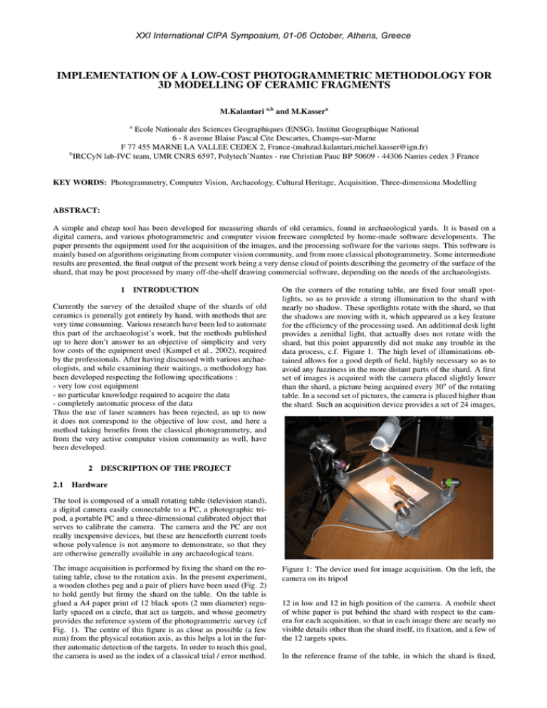
XXI International CIPA Symposium, 01-06 October, Athens, Greece IMPLEMENTATION OF A LOW-COST PHOTOGRAMMETRIC METHODOLOGY FOR 3D MODELLING OF CERAMIC FRAGMENTS M.Kalantari a,b and M.Kassera a Ecole Nationale des Sciences Geographiques (ENSG), Institut Geographique National 6 - 8 avenue Blaise Pascal Cite Descartes, Champs-sur-Marne F 77 455 MARNE LA VALLEE CEDEX 2, France-(mahzad.kalantari,michel.kasser@ign.fr) b IRCCyN lab-IVC team, UMR CNRS 6597, Polytech’Nantes - rue Christian Pauc BP 50609 - 44306 Nantes cedex 3 France KEY WORDS: Photogrammetry, Computer Vision, Archaeology, Cultural Heritage, Acquisition, Three-dimensiona Modelling ABSTRACT: A simple and cheap tool has been developed for measuring shards of old ceramics, found in archaeological yards. It is based on a digital camera, and various photogrammetric and computer vision freeware completed by home-made software developments. The paper presents the equipment used for the acquisition of the images, and the processing software for the various steps. This software is mainly based on algorithms originating from computer vision community, and from more classical photogrammetry. Some intermediate results are presented, the final output of the present work being a very dense cloud of points describing the geometry of the surface of the shard, that may be post processed by many off-the-shelf drawing commercial software, depending on the needs of the archaeologists. 1 INTRODUCTION Currently the survey of the detailed shape of the shards of old ceramics is generally got entirely by hand, with methods that are very time consuming. Various research have been led to automate this part of the archaeologist’s work, but the methods published up to here don’t answer to an objective of simplicity and very low costs of the equipment used (Kampel et al., 2002), required by the professionals. After having discussed with various archaeologists, and while examining their waitings, a methodology has been developed respecting the following specifications : - very low cost equipment - no particular knowledge required to acquire the data - completely automatic process of the data Thus the use of laser scanners has been rejected, as up to now it does not correspond to the objective of low cost, and here a method taking benefits from the classical photogrammetry, and from the very active computer vision community as well, have been developed. 2 2.1 On the corners of the rotating table, are fixed four small spotlights, so as to provide a strong illumination to the shard with nearly no shadow. These spotlights rotate with the shard, so that the shadows are moving with it, which appeared as a key feature for the efficiency of the processing used. An additional desk light provides a zenithal light, that actually does not rotate with the shard, but this point apparently did not make any trouble in the data process, c.f. Figure 1. The high level of illuminations obtained allows for a good depth of field, highly necessary so as to avoid any fuzziness in the more distant parts of the shard. A first set of images is acquired with the camera placed slightly lower than the shard, a picture being acquired every 30o of the rotating table. In a second set of pictures, the camera is placed higher than the shard. Such an acquisition device provides a set of 24 images, DESCRIPTION OF THE PROJECT Hardware The tool is composed of a small rotating table (television stand), a digital camera easily connectable to a PC, a photographic tripod, a portable PC and a three-dimensional calibrated object that serves to calibrate the camera. The camera and the PC are not really inexpensive devices, but these are henceforth current tools whose polyvalence is not anymore to demonstrate, so that they are otherwise generally available in any archaeological team. The image acquisition is performed by fixing the shard on the rotating table, close to the rotation axis. In the present experiment, a wooden clothes peg and a pair of pliers have been used (Fig. 2) to hold gently but firmy the shard on the table. On the table is glued a A4 paper print of 12 black spots (2 mm diameter) regularly spaced on a circle, that act as targets, and whose geometry provides the reference system of the photogrammetric survey (cf Fig. 1). The centre of this figure is as close as possible (a few mm) from the physical rotation axis, as this helps a lot in the further automatic detection of the targets. In order to reach this goal, the camera is used as the index of a classical trial / error method. Figure 1: The device used for image acquisition. On the left, the camera on its tripod 12 in low and 12 in high position of the camera. A mobile sheet of white paper is put behind the shard with respect to the camera for each acquisition, so that in each image there are nearly no visible details other than the shard itself, its fixation, and a few of the 12 targets spots. In the reference frame of the table, in which the shard is fixed, XXI International CIPA Symposium, 01-06 October, Athens, Greece this set of images is equivalent to 12 sets of stereoscopic pairs with exactly the same base length (bases that are more or less vertical, and in any case converging in the same point, somewhere on the rotation axis of the table), regularly arranged in 12 directions every 30o of the 3D space. The manual rotation of the table is performed so that the targets have always the same position in the images, which makes easy an automatic detection of these spots in the photogrammetric image process. 2.2 Data processing The pictures are transferred into the PC, from which are triggered the acquisitions. One may suppose that the camera has been calibrated previously in a classic way. If it has not been the case, a three-dimensional object of decimetric size is used, equipped with targets, and for which a complete dimensional measurement is known. Figure 3: Shades of the pair of successive images of the shard with the superimposition of the Harris points selected after a Ransac filtering, and the vectors joining the homologous points • Epipolar re-sampling of the two images. c.f. Figure 4 Figure 2: Archaeological shard used for the first tests The reference frame used is the one of the rotating table with the image of the 12 targets spots fixed on it. Ox is in the plane of the tray, materialized by the spots targets whose coordinates are known, Oz being the axis of rotation (generally vertical), and Oy so as to get a reference frame of direct sense. The data processing is a classical photogrammetric (Kasser and Egels, 2001) / computer vision process (Ma et al., 2003),(Hartley and Zisserman, 2004). In fact, photogrammetric approach is somewhat different from the computer vision one, so that there are not many opportunities to take benefit from the two technologies simultaneously. Just to make it short, in photogrammetry generally the camera is calibrated, its focal length and its principal point of autocollimation (ppa) are known, and the distortion polynomial characteristic of the optics as well. In this case, only 5 parameters have to be determined to produce the relative orientation for the stereoscopic pair of images. Thus the ”essential” matrix is the normal work tool for photogrammetrists. In computer vision, generally the intrinsic parameters of the optics are unknown, and for that reason the geometric problem is a bit more complicated. Instead of the ”essential” matrix, the ”fundamental” matrix is used in order to provide the relative orientation, with 8 parameters to solve. The present work uses a set of algorithms, available on Internet in various sites, that are issued from these two domains (Ma et al., 2003), (Hartley and Zisserman, 2004). The succession of operations is the following : • In each pair of images (with a vertical base), automatic extractions of interest points in the two images, and research of homologous ones. c.f. Figure 3 • Computation of the fundamental matrix. Figure 4: The two images resampled in epipolar geometry • Dense correlation of the two epipolar-sampled images (matching is considerably faster and simpler in epipolar-sampled images), production of an image of disparities. c.f. Figure 5 Figure 5: The disparity model obtained after the dense matching phase • Using the disparities, production of a cloud of points. c.f. Figure 6 XXI International CIPA Symposium, 01-06 October, Athens, Greece this would lead to a computation time probably judged as prohibitive by users, and the complexity of such a computation, even if classical for professional photogrammetrists, would not be easy to fit in a fully automatic processing chain to be used by non specialists. Thus a much simpler approach has been selected, whose final precision is acceptable. In each image, amongst all the interest points, the targets spots are detected. In the 12 images acquired in the ”low” position, then in the 12 in ”high” position of the camera, the targets occupy a place which is constant from image to image, and the size and contrast of the spots is such that they are detected by the Harris algorithm. Thus an automatic identification of these targets behaves correctly. Knowing the exact 3D location of each of these targets spots allows then to provide the 3D coordinates for all the points that will be extracted. The complete survey of the ceramics shard is obtained through a classical epipolar dense matching of the successive pairs of images with a vertical base, one image in the ”low” position of the camera and the corresponding image in the ”high” position. Each pair provides a cloud of points, and the fusion of theses 12 clouds in an unique one relies entirely on the quality of the acquisition of the targets spots in each image, and of course on the quality of their 3D coordinates. The cloud of points thus gotten is used with classic software, and it is exploited according to the archaeologist’s needs (meridian sections, plane representation of the decorations, etc.). This part of the work is not developed here, the present paper being devoted only to the geometric acquisition of the shape of the shard. 3 Figure 6: The 3D result, around 150 000 points • Using the identification of the targets spots, the coordinates of the cloud of points are transferred into the reference frame of the rotating table, and thus of the shard. • Continuation of the work with all of the 12 stereoscopic pairs and production of an unique cloud of points. A detector of interest points (points of Harris) is used, that succeeds easily to extract in every image a very large set of interest points (Harris and Stephens, 1988). These points are then put in correspondence in an automatic way, using a RANSAC filtering (Fischler and Bolles, 1987). Other methodologies are available in order to detect interest points, such as the SIFT (points of Lowe,(Lowe, 2003)). But the present work is based upon the use of various software developments freely available through Internet, and if many excellent Harris detectors are widely accessible, the availability of SIFT detectors is not yet wide enough, even if the initial tests have shown that Lowe points are probably more efficient than Harris ones on such objects as shards. At this step of the work, the goal is to compute the fundamental matrix that allows to put in correspondence with a correct geometry the pair of images. To achieve this computation, only 8 (non coplanar) interest points are necessary : thus anybody understands that, provided the RANSAC filtering is efficient, it is always possible to select 8 satisfying interest points among the hundreds that are produced, and then it is not compulsory to work with the best possible detector of interest points. The most acomplished (and precise) way of relative orientation of the images would be to compute a bundle adjustment with all the Harris points, checked through the RANSAC filtering. But RESULTS AND DISCUSSION The precision obtained on the archaeological shard presented in Figure 7 is far better than 1 mm, which seems correct for the needs expressed, and is perfectly compatible with the requested technical means. The clouds of points acquired with this process are extremely dense, and they have to be post-processed by classical software adapted to these type of data, and the present work does not require to go further in this direction. The only particular material required is the rotating table and the spotlights, whose total cost is only of a few tens of euros. 4 CONCLUSIONS AND FUTURE WORK The next steps beyond the present work will be to link all the various software used here, either downloaded or developed, so as to provide a tool with an acceptable ergonomy. The goal being to provide this tool to non specialists of computer vision or photogrammetry, it is easy to understand that there is still the matter for a significant amount of informatics work. But the outputs of this project nevertheless sound quite promising, even at this early level of development : it must be considered that the reuse of all the key photogrammetric software available on Internet allows to solve for all the technologically difficult parts of the project. This point makes all the difference for today researchers, if compared with the former generation. XXI International CIPA Symposium, 01-06 October, Athens, Greece REFERENCES Capel, D., Fitzgibbon, A., Kovesi, P., Werner, T., Wexler, Y. and A.Zisserman, 2005. Matlab functions for multiple view geometry. http://www.robots.ox.ac.uk/ vgg/. Fischler, M. A. and Bolles, R. C., 1987. Random sample consensus: A paradigm for model fitting with applications to image analysis and automated cartography. In: M. A. Fischler and O. Firschein (eds), Readings in Computer Vision: Issues, Problems, Principles, and Paradigms, Kaufmann, Los Altos, CA., pp. 726–740. Harris, C. and Stephens, M., 1988. A combined corner and edge detection. In: Proceedings of The Fourth Alvey Vision Conference, pp. 147–151. Hartley, R. I. and Zisserman, A., 2004. Multiple View Geometry in Computer Vision. Second edn, Cambridge University Press, ISBN: 0521540518. Huynh, D. Q., 2003. Matlab functions for computer vision. http://www.csse.uwa.edu.au/ du/. Figure 7: A raw representation of the points resulting from the dense matching, with the grey levels of the corresponding pixels. The black dots correspond to missing data due to a lack of correlation Kampel, M., Sablatnig, R. and Mara, H., 2002. Automated documentation system for pottery. In: N. Magnenat-Thalmann and J. Rindel (eds), Proc. of 1st International Workshop On 3d Virtual Heritage, Geneva, Switzerland, pp. 14–20. Kasser, M. and Egels, Y., 2001. Digital Photogrammetry. Taylor Francis Ltd. 5 ACKNOWLEDGEMENTS This work is part of the doctoral studies of M. Kalantari, supported by IGN-France and the doctoral school STIM from IRCCYN Laboratory / Nantes University. The authors have extensively used software developments freely available on Internet for research purposes, that provided the key parts of all the algorithms developed. Thus we thank here : - Peter Kovesi, for Harris points extraction and fundamental matrix computation (Kovesi, 2007) - De Huynh, for the epipolar rectification (Huynh, 2003) - Lawrence Zitnick, for dense epipolar matching(Zitnick, 2003), (Zitnick and Kanade, 2000) - Richard Hartley and Andrew Zisserman(Hartley and Zisserman, 2004), (Capel et al., 2005), for various code elements provided in their unvaluable book. Kovesi, P., 2007. Matlab and octave functions for computer vision and image processing. http://www.csse.uwa.edu.au/ pk/Research/MatlabFns/index.html. Lowe, D., 2003. Distinctive image features from scale-invariant keypoints. In: International Journal of Computer Vision, Vol. 20, pp. 91–110. Ma, Y., Soatto, S., Kosecka, J. and Sastry, S. S., 2003. An Invitation to 3-D Vision: From Images to Geometric Models. SpringerVerlag. Zitnick, C. L., 2003. A cooperative stereo vision vision. http://www.csse.uwa.edu.au/ du/. Zitnick, C. L. and Kanade, T., 2000. A cooperative algorithm for stereo matching and occlusion detection. IEEE Transactions on Pattern Analysis and Machine Intelligence, PAMI 22(7), pp. 675– 684.


