POSSIBLE APPLICATIONS OF PANORAMIC PHOTOGRAMMETRY CONCERNING CONSTRUCTION MACHINES AND BUILDING SITES
advertisement
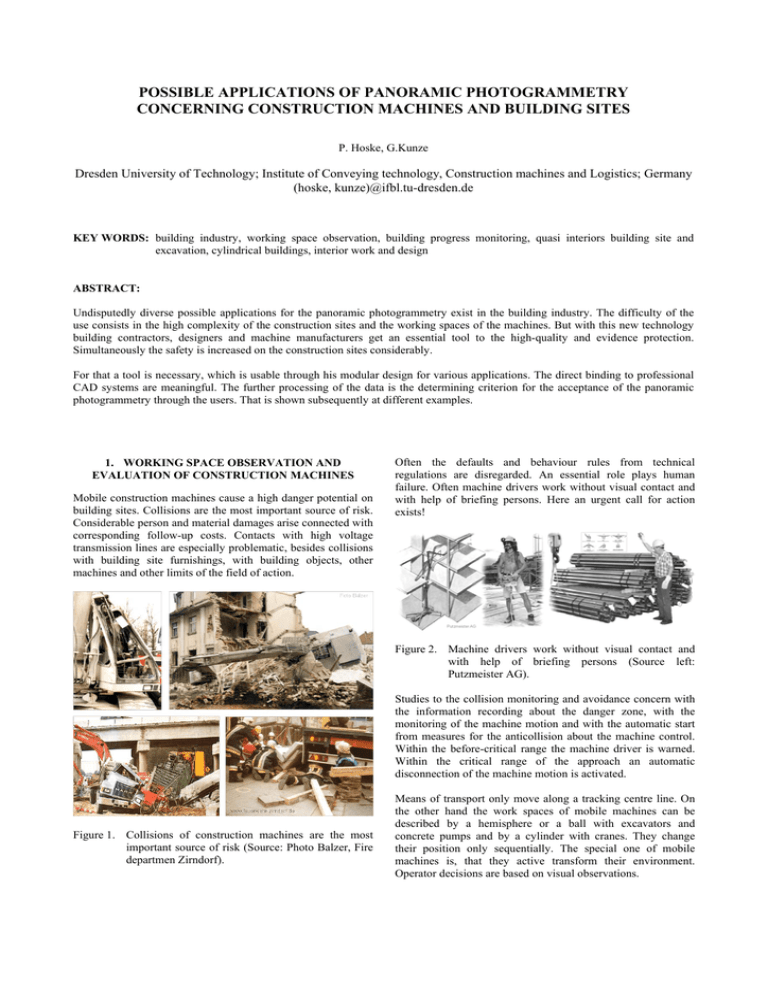
POSSIBLE APPLICATIONS OF PANORAMIC PHOTOGRAMMETRY CONCERNING CONSTRUCTION MACHINES AND BUILDING SITES P. Hoske, G.Kunze Dresden University of Technology; Institute of Conveying technology, Construction machines and Logistics; Germany (hoske, kunze)@ifbl.tu-dresden.de KEY WORDS: building industry, working space observation, building progress monitoring, quasi interiors building site and excavation, cylindrical buildings, interior work and design ABSTRACT: Undisputedly diverse possible applications for the panoramic photogrammetry exist in the building industry. The difficulty of the use consists in the high complexity of the construction sites and the working spaces of the machines. But with this new technology building contractors, designers and machine manufacturers get an essential tool to the high-quality and evidence protection. Simultaneously the safety is increased on the construction sites considerably. For that a tool is necessary, which is usable through his modular design for various applications. The direct binding to professional CAD systems are meaningful. The further processing of the data is the determining criterion for the acceptance of the panoramic photogrammetry through the users. That is shown subsequently at different examples. 1. WORKING SPACE OBSERVATION AND EVALUATION OF CONSTRUCTION MACHINES Mobile construction machines cause a high danger potential on building sites. Collisions are the most important source of risk. Considerable person and material damages arise connected with corresponding follow-up costs. Contacts with high voltage transmission lines are especially problematic, besides collisions with building site furnishings, with building objects, other machines and other limits of the field of action. Often the defaults and behaviour rules from technical regulations are disregarded. An essential role plays human failure. Often machine drivers work without visual contact and with help of briefing persons. Here an urgent call for action exists! Figure 2. Machine drivers work without visual contact and with help of briefing persons (Source left: Putzmeister AG). Studies to the collision monitoring and avoidance concern with the information recording about the danger zone, with the monitoring of the machine motion and with the automatic start from measures for the anticollision about the machine control. Within the before-critical range the machine driver is warned. Within the critical range of the approach an automatic disconnection of the machine motion is activated. Figure 1. Collisions of construction machines are the most important source of risk (Source: Photo Balzer, Fire departmen Zirndorf). Means of transport only move along a tracking centre line. On the other hand the work spaces of mobile machines can be described by a hemisphere or a ball with excavators and concrete pumps and by a cylinder with cranes. They change their position only sequentially. The special one of mobile machines is, that they active transform their environment. Operator decisions are based on visual observations. Measuring procedures are needed, that determine the described working space effective, complete or partial, on- or off-line. Because of visually made decisions the use of picture giving procedures is reasonable. Different testing methods and assistance systems are the first step. A further step is the development of control systems for autonomously working machines. Also demands of the visual presentation of the measurement results, of the preservation of evidence and of standards must be considered in this case. Already assigned systems with crane are mechanical barriers. Electromagnetic sensors warn of high voltage transmission lines. Their functionality is not always ensured. Ultrasonic distance sensors are another possibility. Figure 3. Means of transport move along a trecking centre line, while the working space of mobile construction machines are hemisphere, ball or cylinder (Source left: Frauenhofer Institut Verkehrs- und Ifrastruktursysteme) Studies should begin for reduced situations. Such complex building sites such as Munich Riem are not yet controllable with today's technical means. The degrees of freedom of excavator movement show that the working space has a spherical shape. Time parameters are to be considered also. The revolving platform of an excavator can turn around the own axis 7 times per minute. Figure 6. The Complex building site Munich Riem (Source: Züblin). 2. BUILDING PROGRESS MONITORING Figure 4. Degrees of freedom of an excavator. A picture-supported building progress monitoring was carried out on the large-scale building site Munich Riem. The period was 15 months and cooperation partners were from company Kaiser-BRB Baucontrol. About 400 overview photos were provided mainly from the crane point of view. The real building situation was prepared afterwards graphicly and expressive photos for proof documentation were selected. With building site committing and on basis of the photo material monthly the finished construction units were registered. The completion degree was calculated floor wise and was marked colored on simplified CAD designs. Figure 7. Monthly building progress, floor wise (left) and building progress for one floor (right). Figure 5. The extreme working space of a concrete pump is up to 100 m (Source: Putzmeister AG). A building site is quasi an interior and rotation line cameras have a sufficiently high resolution for large building sites. Therefore the use from panorama cameras is useful to the building progress documentation. Different camera locations are to be examined, for instance high tripod on carcass or neighbouring building or a crane point of view. It is to consider that a building crane also swings with stop accordingly. That causes picture errors. The angle of photography proves as problematic. The photographs must be realized sequentially with sloping camera. Another possibility is to lead the CCD line like a tilted truncated cone. Display spaces included twice are to be calculated out. The impression of a panoramic photograph is different from that of an even sensor. Therefore possibly picture reworks are necessary. Figure 9. Planning of excavations (Source: Internet). Figure 8. Different camera locations and problematic angles of photography are to be examined. Continuous photogrammetric photographs to the quality assurance failed because of necessary correlations. That was too complex for the construction supervisors. Revision picture plans formed an exception. Possibly new applications result from the high resolution of the panoramic photos in combination with fixed well visible construction site references. If the display data can be reduced, it is possible to think about Internet applications. In this way it becomes a tool for owners and designers. The building progress documentation in practice received great recognition. In this way the building firm could prove the building progress opposite the owner and its commercial coworkers convincingly. Moneys were accelerated released. That meant action freedom for the building firm. 3. QUASI INTERIOR – BUILDING SITE A building site represents quasi an interior. Special demands result in the case of intra-urban gap development. For the process of planning a recording of the initial situation is necessary. That includes the measuring of the ground and the production of a simple digital terrain model, the measuring of drive ways, bordering buildings of the neighbours and special elements like trees, supply lines etc.. Nowadays measurement systems are used for that, like tacheometer, laser distance measuring instrument, DGPS-system (differential global positioning system). Invested time and money for the operations scheduling are less and less. Therefore external surveyors are prepared bad or not instructed. Often all requirements are not known at the beginning of the job. Therefore the designers do not get the necessary information, what leads to incorrect planning. The data are needed for excavation planning. Decisions are to be made about timbering, sloping, underpinning of neighbouring buildings, transplantation of trees etc.. A second application is the planning of building site facilities, like crane locations including their mechanical barriers, supply installations, material stores, building containers, ways. The pictures already shows the deficits at data to the neighbouring buildings. The before-mentioned sketches are a component of planning of safety and health protection on building sites, which is required by law in Germany. Figure 10. Planning of site facilities (Source: Bilfinger Berger) A tool is needed, with whose assistance necessary measures can be determined during the planning phase in the office. Picturegiving procedures are particularly suitable for that. The picture evaluation can take place temporally independent from the process of the photo. In addition various picture interpretations are possible. The evaluation can be carried out semiautomatically, with multi image or stereo methods. Corresponding points can be marked manually. The direct binding to CAD systems is very meaningful. Photogrammetry functions should replace the pointer of mouse. That means the 2D- or 3D- symbols are selected in the CAD system and the coordinates or measurements are determined about the photogrammetric evaluation. That is represented in the picture at the example of the tree position. The size and extent of the tree can be determined similarly. Figure 11. Photogrammetry functions should replace the pointer of mouse in CAD systems (Source: TU Dresden, Pit Cup GmbH). 4. QUASI INTERIOR – EXCAVATION DGPS systems and tacheometry systems are used for the quantity survey of earth bodies or the control of earthworking machines. Photogrammetric procedures are employed for the preservation of evidence by the police. The example of the soil slope shows, that for mass determination of geometrically diffuse earth bodies digital terrain model are suitable. The mass determination takes place according to the prism method. Figure 14. Public clients wish the account of achievement of excavations by the profile method, but modelling by expert object models (3D-earth-body-elements) is more useful. That includes the comparison of the start ground (simplified) with the target model (target plan) and the real excavation. Flatter slopes and broader working spaces are not paid. Masses in motion are to be dissected according to soil type, excavation and removal on dump or intermediate storage etc.. The correction of the excavation is carried out still manually. Figure 12. Geometrically diffuse earth bodies are constructed by digital terrain model. Excavations represent a special earth body form. They are geometrically defined and quasi interiors. Figure 15. The Account of achievement must be carried out according to the standards (Correction of excavation mass). Figure 13. Excavations are special earth body forms geometrically defined and quasi interiors (Source: Internet). Public clients still wish the account of achievement after the profile method. In the example point coordinates were determined with tacheometer. Because of its interior suitability and high picture resolution the panoramic photogrammetry seems suitable for a proof-safe achievement account with excavations. Because of forced rims digital terrain models with excavations do not prove as effective with excavations. 3Dearth-body-elements (expert object models, slope and excavation bodies,) would be sufficient exactly, are manage with less measurement points and include knowledge of experts. Procedures of the quantity survey conforming to standards are to be integrated. The acceptance of the clients is a condition for the practice introduction of new procedures for account. 5. INNER SURFACE OF HOLLOW CYLINDERS With the help of panoramic photogrammetry the internal lateral surface of hollow cylinders can be seized very well. The curved surface is almost perpendicularly taken up. Hollowcylindric structures represent sewerage systems, tunnel shafts, industrial buildings such as high furnaces and chimneys, vault and tower structures. The adjustment of the axis of rotation of the camera takes place according to the building axis, perpendicularly or horizontal. Because of the aggressive environment in the sewerage autonomously working robots are to be used for joint renovating. Picture-giving procedures for the control are enclosed. But research work did not lead yet to desired success. It is to be tested which role the panoramic photogrammetry can play for the quality assurance in the production process of cylindrical components (for example tube elements, in German „Tübbing“). 6. INTERIOR WORK AND DESIGN Figure 16. The inner surface of hollow cylinder-like technical buildings must be represented for damages mapping. The surface information are used for the damage mapping. For quantity survey adapted image analysis programs and specific statistic software are to be used. For example joint length, has to be repaired, can be determined automatically. The size of manual marked stones, which should be exchanged, is measurable. Because of optical (exposed concrete ) and technical (sealing) requirements concrete pores must not exceed a special number and size. Figure 17. Image analysis programs and specific statistic software is used for quantity survey, fore instance for statistic of concrete pores. Manufacturers of special designed restaurant equipment work today national and European-wide. The quantity survey is carried out by the local fitters and not by constructing engineers. That leads to information losses. Special structure dimensions must be controlled. Constructing engineers need information about floor edges and colours, tile edges and joints. They must know the position of the installations for supplying and disposing of water, electricity, gas and cooling. A tool is needed, with whose assistance during construction processes all necessary dimensions can be determined. Thus also not foreseeable problems can be solved faster. Figure 18. Manufacturers of special designed restaurant equipment need a tool for determining all dimensions during construction processes to reduce information losses (Source: Ascobloc GastroGerätebau GmbH).
